A–2
PacketMax 5000 Installation and Operation Manual, 10007678 Rev J
Chapter A. Event Reporting
inputs shall be optically isolated from the rest of the system. Reset is accom-
plished by asserting a voltage differential from 3.3 VDC to –48 VDC for
between 200ms and 300ms.
The supported voltage range shall be from 0 to –48VDC continuous, up to –
60VDC at a 50% duty cycle, and up to –72VDC at a 30% duty cycle. The cur-
rent drawn by this input may be as high as 12mA with no damage resulting
from a reversal in polarity.
A.2 PacketMax 5000 and PacketMax 100 Alarms
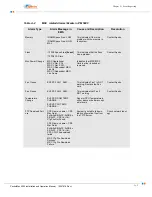
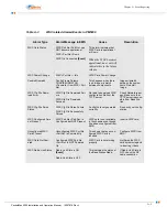
shows the MSC Alarms that are generated in the base station.
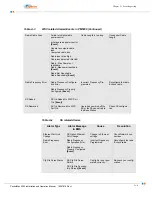
shows the WSC Alarms that are generated in the base Station.
NOTE:
Events are highlighted in brackets in the following tables.
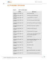
Table A-1
Pin Description of Telco
Pin
Description
1
Minor Reset+
2
Minor Reset+
3
Major Reset-
4
Major Reset-
5
Critical Alarm-NO
6
Critical Alarm-NC
7
Critical Alarm-Com
8
Minor Alarm-NO
9
Minor Alarm-NC
10
Minor Alarm-COM
11
Major Alarm-NO
12
Major Alarm-NC
13
Major Alarm-COM
14
Power Alarm-NO
15
Power Alarm-Com
Summary of Contents for PacketMAX 5000
Page 10: ...Preface Preface vi PacketMax 5000 Installation and Operation Manual 10007678 Rev J ...
Page 14: ...Table Of Content TOC 4 PacketMax 5000 Installation and Operation Manual 10007678 Rev J ...
Page 146: ...E 4 PacketMax 5000 Installation and Operation Manual 10007678 Rev J Chapter E Certifications ...
Page 150: ...F 4 PacketMax 5000 Installation and Operation Manual 10007678 Rev J Chapter F Troubleshooting ...

