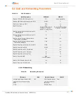
D–11
PacketMax 5000 Installation and Operation Manual, 10007678 Rev J
Chapter D. System Specifications
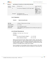
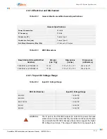
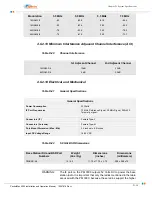
4.6.1.6 Electrical and Mechanical
Table D-12
General Electrical and Mechanical Specifications
Table D-13
BSR Dimensions
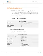
4.6.1.7 Input DC Voltage Range
Table D-14
Input DC Voltage Range
WARNING:
The IF port on the PM 3000 outputs 52 Volts DC to power the base
station radio. It is important that only the radios mentioned in the table
are used with the PM 3000; because, these radios support the higher
DC voltage input range. The usage of radios that only support up to
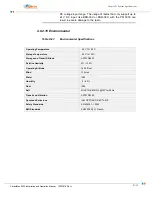
General Specifications
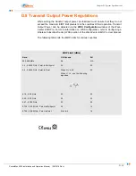
Power Consumption
30 Watts
IF Frequency
70 MHz
Connectors (IF)
Female Type-F
Connectors (Antenna)
Female Type-N
Pole Mount Dimension (Max / Min)
2.5 inches to 4.5 inches
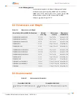
Base Station IDU and BSR Part
Numbers
Weight
(Lbs / Kg)
Dimensions
(inches)
Dimensions
(millimeters)
PM-BSR-33 and PM-BSRX-33
10 / 4.5
11.75 x 11.75 x 2.75
298 x 298 x 70
PM-BSR-35 and PM-BSRX-35
10 / 4.5
11.75 x 11.75 x 2.75
298 x 298 x 70
BSR Part Number
Input DC Voltage Range
BSR-33X
18-36 VDC
BSR-35X
18-36 VDC
BSR- 35X-48
18-54 VDC
BSR-33
18-54 VDC
BSR-35
18-54 VDC
Summary of Contents for PacketMAX 5000
Page 10: ...Preface Preface vi PacketMax 5000 Installation and Operation Manual 10007678 Rev J ...
Page 14: ...Table Of Content TOC 4 PacketMax 5000 Installation and Operation Manual 10007678 Rev J ...
Page 146: ...E 4 PacketMax 5000 Installation and Operation Manual 10007678 Rev J Chapter E Certifications ...
Page 150: ...F 4 PacketMax 5000 Installation and Operation Manual 10007678 Rev J Chapter F Troubleshooting ...

