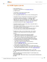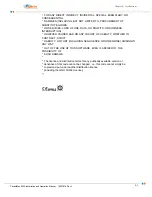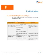
F–3
PacketMax 5000 Installation and Operation Manual, 10007678 Rev J
Chapter F. Troubleshooting
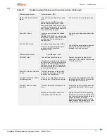
LED sequence unclear
Synchronization- MSC
Master LED- Does not show
green
The card is not inserted fully or prop-
erly.
Since there is one MSC now, this
should always show green. When
there are multiple Base Stations there
would be a master and a slave. In that
case, master card will be green and the
slave will be blinking green.
Check if the card is inserted properly.
Sync LED - Green
There is no synchronization of base
stations.
Indicates OFF if MSC is not in sync and
solid green if MSC is in sync. The Mas-
ter mode and the standby mode is
blinking green.
Check the sync cable connected to the
cables.
Ext. Clk LED - Green
No external clk is connected. (OFF)
Connects the external 10MHz refer-
ence source for PacketMax
signalling. (ON)
Check that the external clock is up and
running. Check cable connection
between clock and sync port.
LED sequence unclear
Shelf Manager - MSC
OOS LED - Red
The card is not safe to remove.
Indicates red, only when the system is
out of service. Out of service indicates
red when the shelf manager detects
that there is a problem. For example,
the power is missing or the MSC card
has functionality issues.
Remove the card only when OOS
shows red. This indicates that the card
it is safe to remove.
Minor LED - Does not indicate
orange
This LED indicates an orange color
only when something is not working
and there is a minor alarm.
Pwr LED - If the Power LED is
not blinking green
This is Power LED. Green indicates
normal power. Off indicates no power.
Check the power supply and look at the
fault manager in EMS. This could also
mean that the IF card is bad.
H/S LED - Does not show
blue LED.
This LED indicates hot swap (blue in
color).
Holding the ejectors at both ends of the
cards will initiate a H/S LED to come
on.
Bootrom is at a higher version or is
incompatible with the firmware.
Upgrade the bootrom after upgrading
the firmware. BS should be operational
with the new firmware, before program-
ming the bootrom of the BS.
Ensure the upgrade procedure of the
Base Station is done properly, as in the
Upgrade Base Station Instructions.
Table F-1
Troubleshooting Problems and Corrective Actions (Continued)
Summary of Contents for PacketMAX 5000
Page 10: ...Preface Preface vi PacketMax 5000 Installation and Operation Manual 10007678 Rev J ...
Page 14: ...Table Of Content TOC 4 PacketMax 5000 Installation and Operation Manual 10007678 Rev J ...
Page 146: ...E 4 PacketMax 5000 Installation and Operation Manual 10007678 Rev J Chapter E Certifications ...
Page 150: ...F 4 PacketMax 5000 Installation and Operation Manual 10007678 Rev J Chapter F Troubleshooting ...

