2–3
PacketMax 5000 Installation and Operation Manual, 10007678 Rev J
Chapter 2. Base Station Components
2.2 5-Slot ATCA Chassis
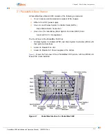
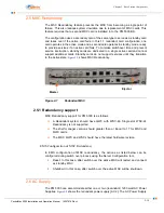
The PM500 Base Station is based on a 5U high ATCA compliant modular chassis.
The chassis contains five physical slots numbered 1 through 5 that accommodate
three different Aperto hot-swappable cards:
Main System Controller (MSC)
Wireless System Controller (WSC-S-24)
Quad Wireless Controller (QWC) (holds up to four WSC-S-48’s)
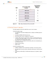
lists and defines the slot positioning rules for the above-listed cards. Fully
populated slots for slots 3, 4 and 5 with three QWC cards, each containing four
WSC-S-48’s, defines the 12 sector system.
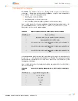
The PM5000 Base Station system assigns a logical port number for each WSC and
is based on this card’s physical slot location in the chassis. The logical port number
acts as the internal address for the card and is used in the CLI, SNMP, and EMS
management interfaces.
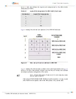
lists and defines the logical port number assignments for the WSC-S-48’s
(installed in a QWC).
Table 2-A
Slot Positioning Requirements for MSC/WSC-S-24/QWC
Slot Number
Required Cards
1
Dedicated MSC (copper of fiber Ethernet interface)
2
Dedicated MSC/WSC (WSC-S-24)
3
One WSC-S-24 or one QWC (each QWC holds up to four WSC-S-
48’s)
4
One WSC-S-24 or one QWC (each QWC holds up to four WSC-S-
48’s)
5
One WSC-S-24 or one QWC (each QWC holds up to four WSC-S-
48’s)
Table 2-B
Logical Port Number Assignments for WSC-S-48’s (Installed in
QWC)
Slot Number
Logical Port Assignments
5
10, 11, 12, 12
4
6, 7, 8, 9
3
2, 3, 4, 5
2
N/A
1
N/A
Summary of Contents for PacketMAX 5000
Page 10: ...Preface Preface vi PacketMax 5000 Installation and Operation Manual 10007678 Rev J ...
Page 14: ...Table Of Content TOC 4 PacketMax 5000 Installation and Operation Manual 10007678 Rev J ...
Page 146: ...E 4 PacketMax 5000 Installation and Operation Manual 10007678 Rev J Chapter E Certifications ...
Page 150: ...F 4 PacketMax 5000 Installation and Operation Manual 10007678 Rev J Chapter F Troubleshooting ...

