2–4
PacketMax 5000 Installation and Operation Manual, 10007678 Rev J
Chapter 2. Base Station Components
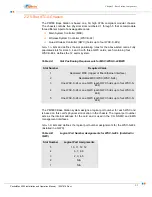
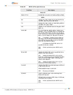
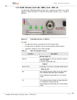
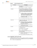
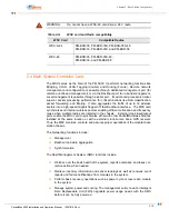
lists and defines the logical port assignments for the WSC-S-48’s
(independent of QWC).
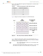
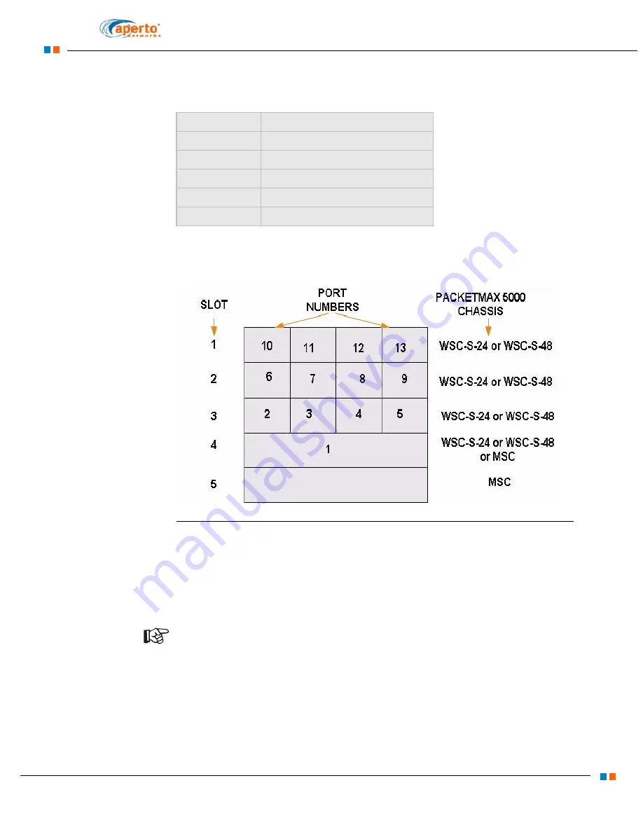
displays the slot and plot numbers on the PM 5000 hardware.
Figure 2-2
Slots and port numbers allotment of PM 5000
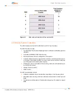
displays the slots and port numbers of a 4 sector base station and
shows a 12 sector base station. Please note that the port numbers are labelled
according to software configuration of the device.
NOTE:
In Element Management System and CLI, while configuring, please
enter the right port number.
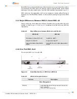
Filler panels (PN PM 5000-FRONT PANEL) should be inserted, in to any unused
slots. Build-to-order systems will include filler panels in any unused slots.
Table 2-C
Logical Port Assignments for WSC-S-24’s (Card only)
Slot Number
Logical Port Assignments
5
10
4
6
3
2
2
1
1
N/A
Summary of Contents for PacketMAX 5000
Page 10: ...Preface Preface vi PacketMax 5000 Installation and Operation Manual 10007678 Rev J ...
Page 14: ...Table Of Content TOC 4 PacketMax 5000 Installation and Operation Manual 10007678 Rev J ...
Page 146: ...E 4 PacketMax 5000 Installation and Operation Manual 10007678 Rev J Chapter E Certifications ...
Page 150: ...F 4 PacketMax 5000 Installation and Operation Manual 10007678 Rev J Chapter F Troubleshooting ...

