4–4
PacketMax 5000 Installation and Operation Manual, 10007678 Rev J
Chapter 4. Installing the Base Station ODU Radio and Antenna
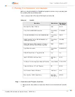
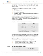
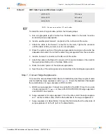
Other Items needed to install the Base Station Radio are:
IF Cable (outdoor rated high quality coax) with two type-F connectors
Short RF Cable to connect BSR to the Antenna
Grounding Cable (AWG 10 or 12, copper stranded, outdoor rated) and two
Coax Surge Protectors (Aperto P/N: PA-SP-OUTDOOR-08 contains two surge
protectors and two grounding wires).
4.3.3 Preparing and Mounting the 3.3 and 3.5 GHz BSR
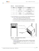
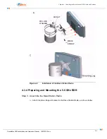
Step 1. Attach Bracket and Grounding Wire to BSR
A.
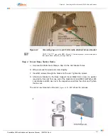
Attach the mounting bracket to BSR using the included screws.
B.
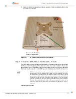
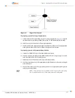
Attach the grounding lug to the radio, as shown in
(PM-BSR-33 and PM-
BSR-35).
NOTE: The grounding lug does not exist on the BSR, the customer must install it.
C.
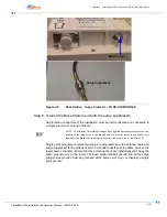
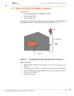
Provide a proper grounding conductor (NEC Section 810-21) long enough to
reach from the Outdoor Unit to the earth ground. Color of the insulator of Ground-
ing conductor should be Green with Yellow strip. The size of the grounding wire
should be AWG 10 or AWG 12.
D.
Attach one end of the conductor to the lug on the radio.
E.
Connect the other end of the grounding conductor to an appropriate earth ground
using a grounding clamp.
NOTE: If you install a grounding electrode separate from the power service ground-
ing electrode system, connect the separate electrode to the grounding system in
accordance with the National Electrical Code (NEC) and local electrical codes.
Summary of Contents for PacketMAX 5000
Page 10: ...Preface Preface vi PacketMax 5000 Installation and Operation Manual 10007678 Rev J ...
Page 14: ...Table Of Content TOC 4 PacketMax 5000 Installation and Operation Manual 10007678 Rev J ...
Page 146: ...E 4 PacketMax 5000 Installation and Operation Manual 10007678 Rev J Chapter E Certifications ...
Page 150: ...F 4 PacketMax 5000 Installation and Operation Manual 10007678 Rev J Chapter F Troubleshooting ...


