2–24
PacketMax 5000 Installation and Operation Manual, 10007678 Rev J
Chapter 2. Base Station Components
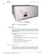
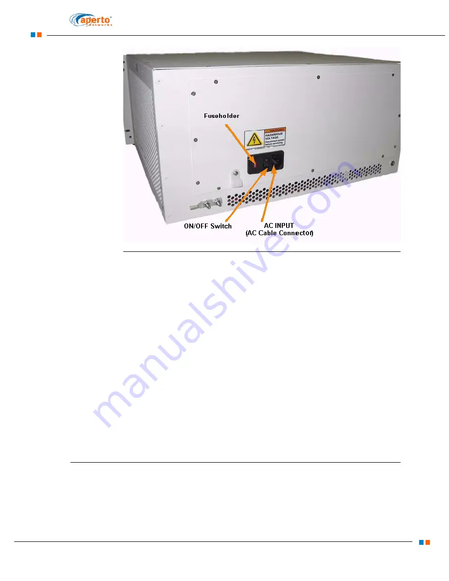
Figure 2-17
AC input- Rear of the PM 5000
2.13.1 Fuse
The AC power supply is protected by a fuse in a holder located next to the power
connector on the rear panel of the Base Station. The fuse is a 10 A, 250 V time-lag
high-breaking fuse, 5 x 20 mm (Bussmann S505-10A). Replacement fused can be
ordered from Aperto parts.
Should this fuse blow, determine and correct the cause (if possible). Then replace the
fuse as follows:
1.
Disconnect the BS’s AC power cord.
2.
Remove the fuse holder.
3.
Remove the fuse from the clips that hold it, and verify that the fuse has blown.
4.
Place a new fuse in the clips.
5.
Snap the fuse holder into the opening in the rear panel.
6.
Reconnect the Base Station Unit’s power cord.
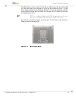
2.14 Base Station Radio
The BSR consists of a RF transceiver (available in a variety of frequency bands) that
connects to a base station antenna (120 degree, 60 degree, 90 degree, or
omnidirectional) through a single coaxial cable, up to a maximum of 200 m (600 ft).
Summary of Contents for PacketMAX 5000
Page 10: ...Preface Preface vi PacketMax 5000 Installation and Operation Manual 10007678 Rev J ...
Page 14: ...Table Of Content TOC 4 PacketMax 5000 Installation and Operation Manual 10007678 Rev J ...
Page 146: ...E 4 PacketMax 5000 Installation and Operation Manual 10007678 Rev J Chapter E Certifications ...
Page 150: ...F 4 PacketMax 5000 Installation and Operation Manual 10007678 Rev J Chapter F Troubleshooting ...

