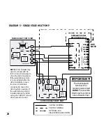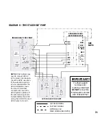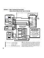
FAN
RELAY
2ND
STAGE
HEAT
1ST
STAGE
HEAT
R
INDOOR HEAT PUMP UNIT
C
G
W1
Y1
W2
Y2
1ST STAGE
COMPRESSOR
2ND STAGE
COMPRESSOR
L1
L2
120
VAC
24
VAC
G
Y1
W1
Y2
W2
RH
RC
O
APRILAIRE MODEL
8870 THERMOSTAT
COMMUNICATION
TERMINALS
B
C
RSB
RSR
RSC
R
RSA
B+
A-
A+
B-
REF
REMOTE
SENSOR(S)
Y1
O
B
W1
C
1ST
STG
COMP.
REV
VALVE
COOL
REV
VALVE
HEAT
DEFROST
OUTDOOR HEAT PUMP UNIT
Y2
2ND
STG
COMP.
SEE
NOTE
IMPORTANT!
The thermostat B
terminal is for
reversing valve-heat.
DO NOT connect the
B terminal to common
side of transformer.
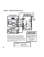
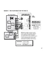
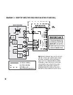
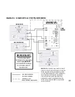
NOTE: HVAC installer may
need to connect 24V AC
to the R and C terminals to
check the HVAC operation.
If the automation system
is to be installed after the
HVAC installation, leave
the R and C terminals
connected to ensure the
HVAC system operates. If
the automation system is
installed before the HVAC
wiring, then DO NOT connect
HVAC wires to R and C.
24V FIELD WIRING
FACTORY WIRING
OPTIONAL 24V
FIELD WIRING (SEE NOTE)
21
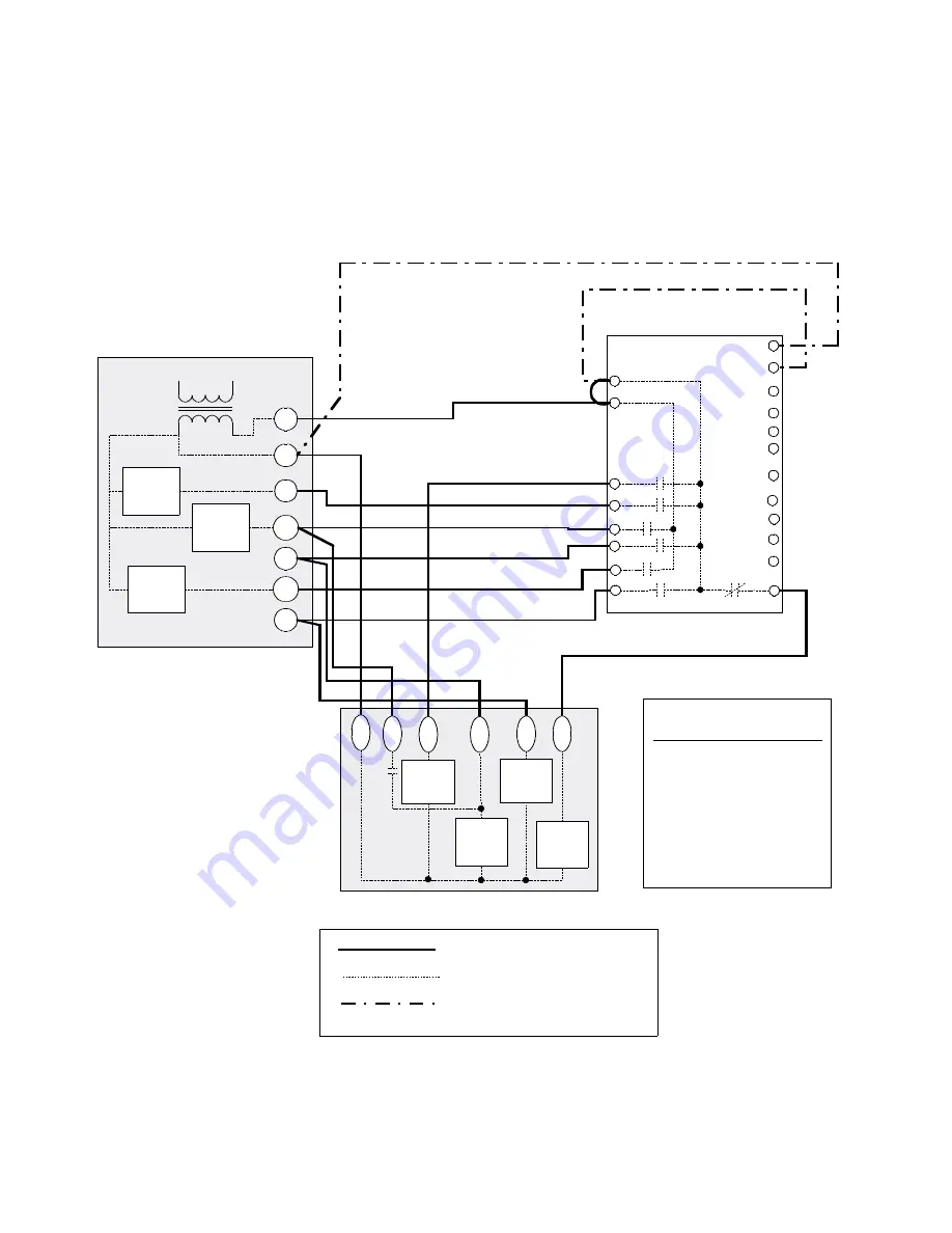
DIAGRAM 6 – TWO STAGE HEAT PUMP
Summary of Contents for 8870
Page 10: ...8 FIGURE 5 ...
Page 17: ...15 FIGURE 8 Cont ...
Page 25: ...23 NOTES ...
Page 26: ...24 NOTES ...
Page 27: ...25 NOTES ...


