ELECTRICAL SYSTEM
6
- 11
RSV mille
6.4.4 CHECKING THE
IGNITION
COILS
◆
Remove both side fairings, see 7.1.26 (REMOVING
NOTE
The following procedure refers to a single coil,
though it is applicable to both.
◆
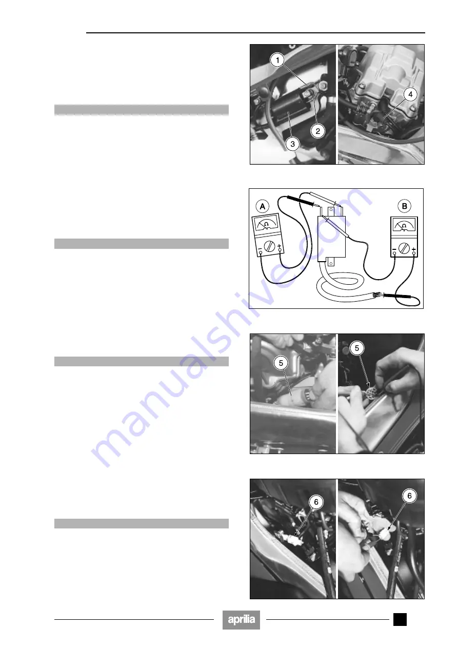
Disconnect the terminals (1-2) from the
ignition
coil (3).
a
CAUTION
When reassembling, make sure the electric terminals
(1-2) are connected up properly.
◆
Slip off the spark plug cap (4) (belonging to the coil of
interest) and disconnect it from the cable.
◆
Measure the values of (A) and (B) indicated in the fig-
ure by means of a pocket tester.
It is important to check the continuity of the primary and
secondary windings.
The reading in Ohms does not necessarily have to be ex-
act but if the windings are sound, the resistance values
must correspond approximately to those indicated.
Standard values:
Measurement (A):
2.8
−
5.2
Ω;
Measurement (B):
9.1
−
16.5 k
Ω.
a
CAUTION
This measuring method is approximate; if possible,
check the correct operation of the coil by replacing it
with another one in perfect condition.
◆
Repeat the procedure for the other coils.
6.4.5 CHECKING THE PICK-UP
With the engine switched off:
◆
Lift the fuel tank, see 2.8 (LIFTING THE FUEL TANK).
◆
Disconnect the two-way connector (5) (coloured white)
and take the measurements (on the engine-side termi-
nals).
a
CAUTION
When reassembling, make sure the electric connec-
tor (5) is plugged in properly.
◆
Using a pocket tester (scale x 100
Ω
), measure the re-
sistance between the terminals of the blue/yellow (B/G)
and white/yellow (Bi/G) cables.
Standard value: 150
−
350
Ω.
If the resistance is infinite (
∞
) or lower than the pre-
scribed level, the sensor must be changed.
6.4.6 CHECKING THE CAMSHAFT POSITION
SENSOR
With the engine switched off:
◆
Lift the fuel tank, see 2.8 (LIFTING THE FUEL TANK).
◆
Disconnect the two-way connector (6) (coloured white)
and take the measurements (on the engine-side termi-
nals).
a
CAUTION
When reassembling, make sure the electric connec-
tor (6) is plugged in properly.
◆
Using a pocket tester (scale x 100
Ω
), measure the re-
sistance between the terminals of the blue/yellow (B/G)
and white/yellow (Bi/G) cables.
Standard value: 150
−
350
Ω.
If the resistance is infinite (
∞
) or lower than the pre-
scribed level, the sensor must be changed.
Summary of Contents for 8140172
Page 1: ...RSV mille MIN 956X Service and repair manual aprilia part 8140172 ...
Page 5: ...0 4 RSV mille NOTE ...
Page 6: ...1 1 RSV mille GENERAL INFORMATION 1 ...
Page 28: ...2 1 RSV mille 1 SERVICE AND SETTING UP 2 ...
Page 84: ...3 1 RSV mille 1 3 ENGINE 3 ...
Page 200: ...4 1 RSV mille 1 2 3 FUEL SUPPLY SYSTEM 4 ...
Page 226: ...5 1 RSV mille 1 2 3 4 COOLING SYSTEM 5 ...
Page 236: ...6 1 RSV mille 6 6 6 6 6 ELECTRICAL SYSTEM 6 ...
Page 239: ...6 4 ELECTRICAL SYSTEM RSV mille 42 0 43 9 54 ...


