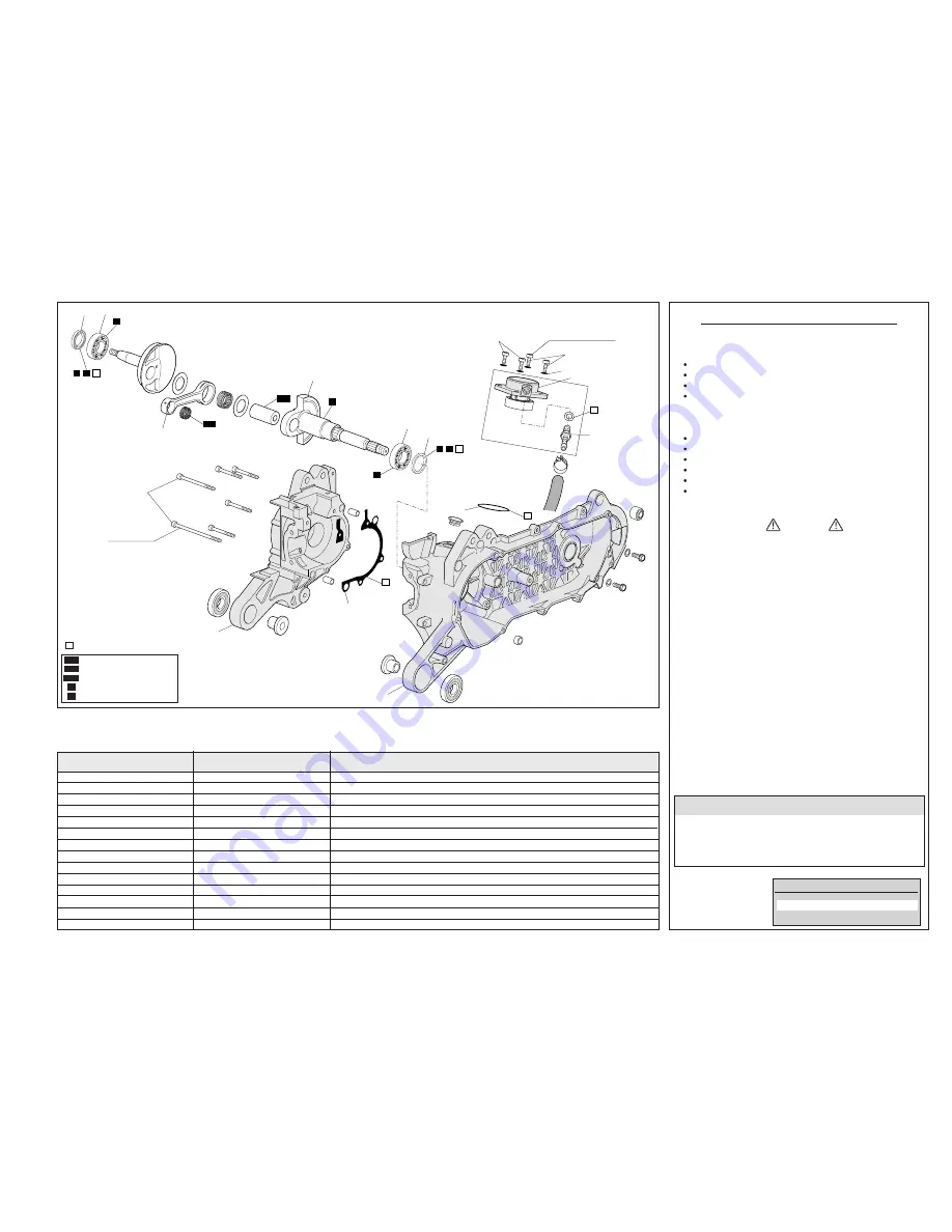
CHECKING WEAR LIMITS
Chart references
Component
Wear limit
DISASSEMBLY SEQUENCE
4-5 Nm (0,4-0,5 kgm)
10 Nm (1 kgm)
1
3
5
2
1
4
6
N
N
N
12
14
10
11
13
G
G
G
G
N
L
G
N
L
OM
OM
15
8
7
9
AIR COMPRESSOR
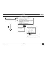
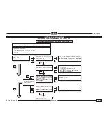
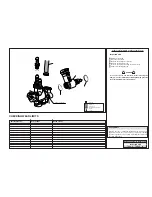
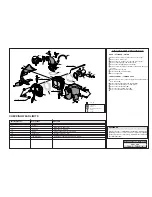
Remove the 4 screws (1) without losing the washers (2).
Remove the compressor (3) from the guard.
Remove the OR (4).
Unscrew the compressor connector (5).
COVER AND CRANKCASE
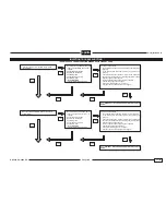
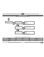
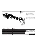
Remove the six cover screws (6).
Separate the RH half (7) from the LH half (8) of the cover.
Remove the gasket (9).
Remove the crankcase (10) from the RH half.
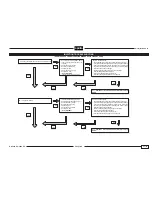
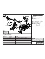
Remove the RH oil guard (11) and LH oil guard (12).
Remove the RH (13) and LH (14) bearing.
WARNING
N.B.: Grease the RH (13) and LH (14) crankshaft main
bearings.
REASSEMBLY
Reverse the order of disassembly instructions, making sure
tightening torques are correct, and all components requiring
grease are greased or, if necessary, replaced with components
specified in the table.
10
Crankcase
10
Crankcase
10
Crankcase
15
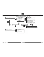
Connecting rod
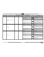
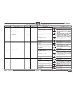
Standard width: 37.95 – 38.10 mm
Off-line tolerance 0.03 mm (measured at two opposite points)
Connecting rod head side play: 0.85 mm (original: 0.75 mm)
Max diameter connecting rod foot: 16.04 mm (original: 16.003 – 16.011 mm)
RELEASE 00 2002 - 09 AIR INJECTION
COVER + CRANKCASE
Chap.6 TABLE
05
: Engine oil
: Gearbox oil
: Molybdenum bisulphuroil
: Grease
: Loctite
OM
O.C.
OBM
G
L
: New item
N

