ENGINE
3
- 10
Pegaso 650 I.E.
Follow
ã
a
CAUTION
To clean the outer parts of the engine use a degreas-
er, brushes and wipers.
Avoid damaging rubber and plastic parts with corro-
sive or penetrating detergents and solvents.
Should the use of a steam cleaner prove necessary,
do not point the high-pressure jets of water, steam or
air at the following parts: wheel hubs, controls on the
right and left handlebars, brake pumps, instruments
and gauges, silencer openings, document compart-
ment, ignition switch/steering lock, electrical compo-
nents.
◆
Clean the outside of the engine thoroughly.
◆
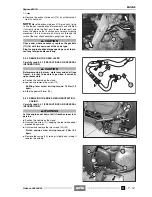
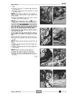
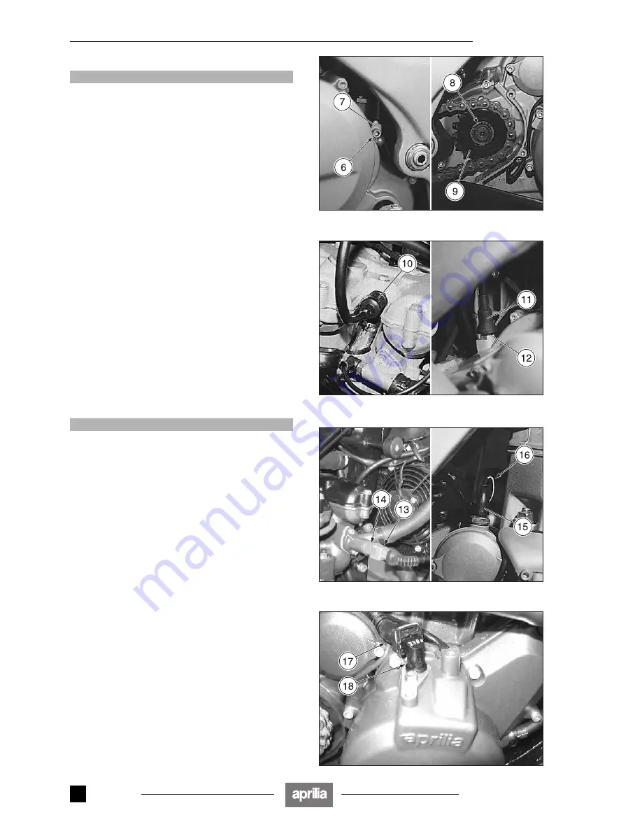
Unscrew and remove the screw (6) and disconnect the
earth cable (7).
◆
Remove the drive pinion protection casing, see 3.2.3
(REMOVING THE DRIVE PINION PROTECTION
CASING).
◆
Remove the stop ring (8).
◆
Slide the drive pinion (9), complete with chain, off the
shaft.
NOTE
If it is difficult to withdraw the drive pinion (9),
slacken the chain slightly, see 2.29.3 (ADJUSTING THE
DRIVING CHAIN).
◆
Remove the drive pinion (9).
NOTE
When reassembling, apply Anti-Seize LOC-
TITE
®
on the inner toothing of the drive pinion (9).
◆
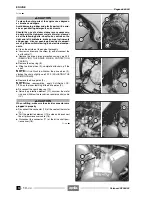
Disconnect the spark plug cap (10).
◆
Raise the protection element (11), unscrew the metal
ring and withdraw the revolution counter control cable
(12).
a
CAUTION
When refitting, make sure the electric connectors are
plugged in properly.
◆
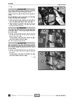
Disconnect the connector (13) of the coolant thermistor
(14).
◆
Pull the protection element (15) aside and disconnect
the oil pressure sensor cable (16).
◆
Disconnect the connector (17) of the drive shaft posi-
tion sensor (18).
Follow
ã
Release 00/2002-02
- 00
Summary of Contents for Pegaso 650 I.E.
Page 11: ...1 1 Pegaso 650 I E GENERAL INFORMATION 1 Release 00 2002 02 00 ...
Page 24: ...GENERAL INFORMATION 1 14 Pegaso 650 I E 1 7 2 GENERIC TOOLS Release 00 2002 02 00 ...
Page 39: ...2 1 Pegaso 650 I E 1 SERVICE AND SETTING UP 2 Release 00 2002 02 00 ...
Page 45: ...SERVICE AND SETTING UP 2 7 Pegaso 650 I E LUBRICATION CHART Release 00 2002 02 00 ...
Page 95: ...3 1 Pegaso 650 I E 1 3 ENGINE 3 Release 00 2002 02 00 ...
Page 99: ...ENGINE 3 5 Pegaso 650 I E Release 00 2002 02 00 ...
Page 113: ...4 1 Pegaso 650 I E 1 2 3 FUEL SUPPLY SYSTEM 4 Release 00 2002 02 00 ...
Page 139: ...5 1 Pegaso 650 I E 1 2 3 4 COOLING SYSTEM 5 Release 00 2002 02 00 ...
Page 149: ...6 1 Pegaso 650 I E 1 2 3 4 5 ELECTRIC SYSTEM 6 Release 00 2002 02 00 ...
Page 152: ...6 4 ELECTRIC SYSTEM Pegaso 650 I E 42 0 43 9 54 00 Release 00 2002 02 ...
Page 190: ...ELECTRIC SYSTEM 6 42 Pegaso 650 I E 7 2 2 Release 00 2002 02 00 ...
Page 193: ...7 1 Pegaso 650 I E 1 2 3 4 5 6 CHASSIS 7 Release 00 2002 02 00 ...
Page 287: ...1 2 3 4 5 6 7 8 1 Pegaso 650 I E 1 2 3 4 5 6 7 REPAIR INFORMATION 8 Release 00 2002 02 00 ...
Page 297: ...REPAIR INFORMATION 8 11 Pegaso 650 I E 8 2 3 FUEL SYSTEM PIPES Release 00 2002 02 00 ...
Page 298: ...REPAIR INFORMATION 8 12 Pegaso 650 I E 8 2 4 ENGINE OIL PIPES Release 00 2002 02 00 ...
Page 304: ...REPAIR INFORMATION 8 18 Pegaso 650 I E Release 00 2002 02 00 ...
Page 305: ...Pegaso 650 I E REPAIR INFORMATION 8 19 Release 00 2002 02 00 ...
Page 306: ...REPAIR INFORMATION 8 20 Pegaso 650 I E Release 00 2002 02 00 ...
Page 307: ...REPAIR INFORMATION 8 21 Pegaso 650 I E Release 00 2002 02 00 ...
Page 311: ... 1 Pegaso 650 I E ANALYTICAL INDEX 00 Release 00 2002 02 ...
Page 317: ...ANALYTICAL INDEX 7 Pegaso 650 I E 9 2IF 0AGE 2IF 0AGE 00 Release 00 2002 02 ...


