COOLING SYSTEM
5
- 3
Pegaso 650 I.E.
$%3#2)04)/.
The centrifugal pump (positioned inside the engine and
driven by the latter) draws coolant and distributes it to the
galleries in the cylinders and in the heads in order to cool
the internal parts of the engine.
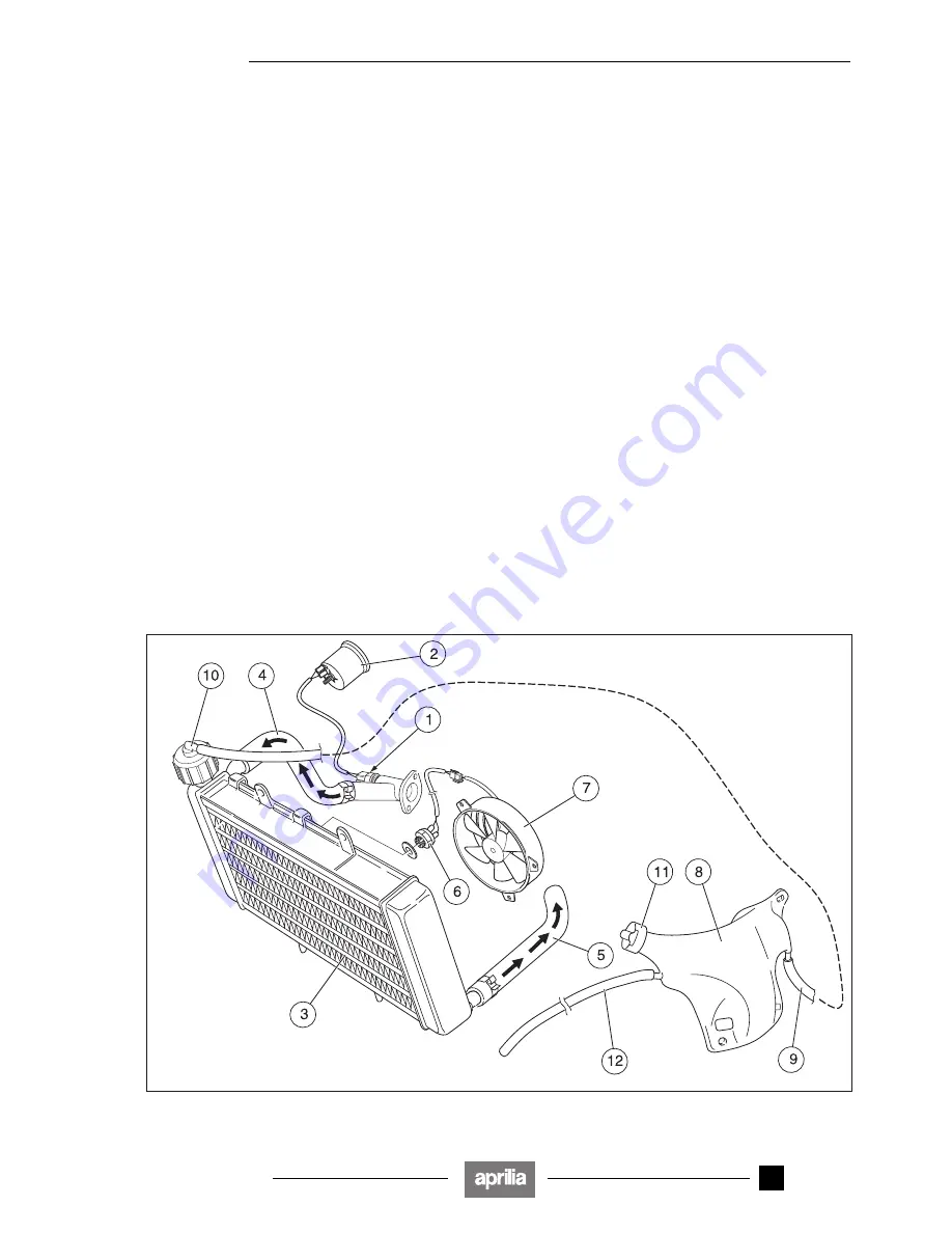
The heated fluid that flows out of the head meets:
– the thermistor (1) that takes its temperature and trans-
mits the measured value to the coolant temperature in-
dicator (2) (on the dashboard) that in turn displays it;
– the radiator (3), through the coupling (4). The liquid first
occupies the upper half of the radiator and then reach-
es its lower half and flows out of the coupling (5);
– the thermal expansion valve (of the type with heat-sen-
sitive wax tablet) that, according to the fluid tempera-
ture, adjusts its flow into the radiator (3).
At 60 – 70 °C the thermal expansion valve starts open-
ing; at approximately 85 °C the valve opens completely
and lets the fluid flow out at the maximum flow rate.
For further information, refer to the engine service and
repair manual, see 0.4.1 (ENGINE SERVICE AND RE-
PAIR MANUALS).
The radiator is provided with the thermal switch (6) that is
activated and starts the electric fan (7) if the fluid temper-
ature in this area reaches 90 °C.
When, thank to the action of the electric fan, the fluid tem-
perature lowers to 80 °C, the thermal switch stops the
electric fan.
The increase in the fluid volume (caused by the tempera-
ture increase) is compensated for in the expansion tank
(8), through the pipe (9).
To check and top up the coolant, refer to the “
MIN
” and
“
MAX
” reference marks, see 2.13 (CHECKING AND
TOPPING UP COOLANT).
For any information regarding the coolant, see 1.2.5
(COOLANT).
Key
1) Air thermistor
2) Coolant temperature indicator
3) Radiator
4) Radiator inlet coupling
5) Radiator outlet coupling
6) Thermal switch
7) Electrofan
8) Expansion tank
9) Compensation pipe
10) Radiator cap
11) Expansion tank cap
12) Breather pipe
Release 00/2002-02
- 00
Summary of Contents for Pegaso 650 I.E.
Page 11: ...1 1 Pegaso 650 I E GENERAL INFORMATION 1 Release 00 2002 02 00 ...
Page 24: ...GENERAL INFORMATION 1 14 Pegaso 650 I E 1 7 2 GENERIC TOOLS Release 00 2002 02 00 ...
Page 39: ...2 1 Pegaso 650 I E 1 SERVICE AND SETTING UP 2 Release 00 2002 02 00 ...
Page 45: ...SERVICE AND SETTING UP 2 7 Pegaso 650 I E LUBRICATION CHART Release 00 2002 02 00 ...
Page 95: ...3 1 Pegaso 650 I E 1 3 ENGINE 3 Release 00 2002 02 00 ...
Page 99: ...ENGINE 3 5 Pegaso 650 I E Release 00 2002 02 00 ...
Page 113: ...4 1 Pegaso 650 I E 1 2 3 FUEL SUPPLY SYSTEM 4 Release 00 2002 02 00 ...
Page 139: ...5 1 Pegaso 650 I E 1 2 3 4 COOLING SYSTEM 5 Release 00 2002 02 00 ...
Page 149: ...6 1 Pegaso 650 I E 1 2 3 4 5 ELECTRIC SYSTEM 6 Release 00 2002 02 00 ...
Page 152: ...6 4 ELECTRIC SYSTEM Pegaso 650 I E 42 0 43 9 54 00 Release 00 2002 02 ...
Page 190: ...ELECTRIC SYSTEM 6 42 Pegaso 650 I E 7 2 2 Release 00 2002 02 00 ...
Page 193: ...7 1 Pegaso 650 I E 1 2 3 4 5 6 CHASSIS 7 Release 00 2002 02 00 ...
Page 287: ...1 2 3 4 5 6 7 8 1 Pegaso 650 I E 1 2 3 4 5 6 7 REPAIR INFORMATION 8 Release 00 2002 02 00 ...
Page 297: ...REPAIR INFORMATION 8 11 Pegaso 650 I E 8 2 3 FUEL SYSTEM PIPES Release 00 2002 02 00 ...
Page 298: ...REPAIR INFORMATION 8 12 Pegaso 650 I E 8 2 4 ENGINE OIL PIPES Release 00 2002 02 00 ...
Page 304: ...REPAIR INFORMATION 8 18 Pegaso 650 I E Release 00 2002 02 00 ...
Page 305: ...Pegaso 650 I E REPAIR INFORMATION 8 19 Release 00 2002 02 00 ...
Page 306: ...REPAIR INFORMATION 8 20 Pegaso 650 I E Release 00 2002 02 00 ...
Page 307: ...REPAIR INFORMATION 8 21 Pegaso 650 I E Release 00 2002 02 00 ...
Page 311: ... 1 Pegaso 650 I E ANALYTICAL INDEX 00 Release 00 2002 02 ...
Page 317: ...ANALYTICAL INDEX 7 Pegaso 650 I E 9 2IF 0AGE 2IF 0AGE 00 Release 00 2002 02 ...


