CHASSIS
7
- 42
Pegaso 650 I.E.
7.2.12 INSTALLING THE FRONT WHEEL
Carefully read 0.5.1 (PRECAUTIONS AND GENERAL
INFORMATIONS).
◆
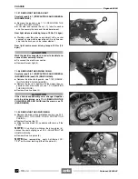
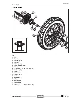
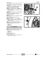
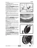
Spread a film of lubricating grease on the whole length
of the wheel pin (1), grease the inside of the speedom-
eter/odometer control (2), see 1.6 (LUBRICANT
CHART).
◆
Position the tang of the speedometer/odometer control
(3) in the appropriate seat of the wheel hub.
◆
Position the odometer control seat correctly, in corre-
spondence with the special antirotation pin (4).
a
CAUTION
While reassembling the wheel, be careful not to dam-
age the brake pipes, discs and pads.
◆
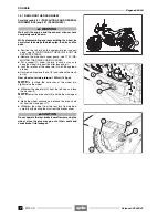
Position the wheel between the fork rods on the support
(5).
a
CAUTION
Proceed with care while inserting the disc in the
brake caliper.
a
WARNING
Danger of injury. Do not introduce your fingers to
align the holes.
◆
Move the wheel until its central hole and the holes on
the fork are aligned.
◆
Position the spacer ring (6) between the wheel hub and
the fork left rod.
◆
Introduce the wheel pin (1) completely from the right
side and tighten it.
Front wheel pin driving torque: 80 Nm (8.0 kgm).
◆
Remove the support (5) that upon disassembly was put
under the tyre.
a
WARNING
Due to the weight and dimensions of the vehicle, the
following operation must be performed by two per-
sons.
NOTE
Weight without driver (ready for starting): 200
kg.
◆
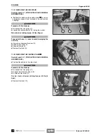
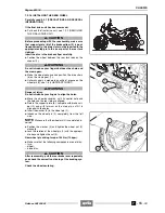
Remove the front support stand, see 1.8 (POSITION-
ING THE VEHICLE ON THE SUPPORT STAND).
◆
Remove the rear support stand, see 1.8 (POSITION-
ING THE VEHICLE ON THE SUPPORT STAND).
◆
With pulled front brake lever, press the handlebar re-
peatedly, thrusting the fork downwards. In this way the
fork rods will settle properly.
◆
Position the vehicle on the stand, see 1.8 (POSITION-
ING THE VEHICLE ON THE SUPPORT STAND).
◆
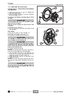
Tighten the two wheel pin clamp screws (7) (right side).
Front wheel pin clamp screw driving torque: 12 Nm
(1.2 kgm).
Release 00/2002-02
- 00
◆
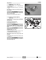
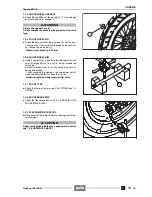
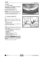
Make sure that the following components are not dirty:
– tyre;
– wheel;
– brake disc.
a
WARNING
After reassembly, pull the front brake lever repeated-
ly and check the correct functioning of the braking
system.
Summary of Contents for Pegaso 650 I.E.
Page 11: ...1 1 Pegaso 650 I E GENERAL INFORMATION 1 Release 00 2002 02 00 ...
Page 24: ...GENERAL INFORMATION 1 14 Pegaso 650 I E 1 7 2 GENERIC TOOLS Release 00 2002 02 00 ...
Page 39: ...2 1 Pegaso 650 I E 1 SERVICE AND SETTING UP 2 Release 00 2002 02 00 ...
Page 45: ...SERVICE AND SETTING UP 2 7 Pegaso 650 I E LUBRICATION CHART Release 00 2002 02 00 ...
Page 95: ...3 1 Pegaso 650 I E 1 3 ENGINE 3 Release 00 2002 02 00 ...
Page 99: ...ENGINE 3 5 Pegaso 650 I E Release 00 2002 02 00 ...
Page 113: ...4 1 Pegaso 650 I E 1 2 3 FUEL SUPPLY SYSTEM 4 Release 00 2002 02 00 ...
Page 139: ...5 1 Pegaso 650 I E 1 2 3 4 COOLING SYSTEM 5 Release 00 2002 02 00 ...
Page 149: ...6 1 Pegaso 650 I E 1 2 3 4 5 ELECTRIC SYSTEM 6 Release 00 2002 02 00 ...
Page 152: ...6 4 ELECTRIC SYSTEM Pegaso 650 I E 42 0 43 9 54 00 Release 00 2002 02 ...
Page 190: ...ELECTRIC SYSTEM 6 42 Pegaso 650 I E 7 2 2 Release 00 2002 02 00 ...
Page 193: ...7 1 Pegaso 650 I E 1 2 3 4 5 6 CHASSIS 7 Release 00 2002 02 00 ...
Page 287: ...1 2 3 4 5 6 7 8 1 Pegaso 650 I E 1 2 3 4 5 6 7 REPAIR INFORMATION 8 Release 00 2002 02 00 ...
Page 297: ...REPAIR INFORMATION 8 11 Pegaso 650 I E 8 2 3 FUEL SYSTEM PIPES Release 00 2002 02 00 ...
Page 298: ...REPAIR INFORMATION 8 12 Pegaso 650 I E 8 2 4 ENGINE OIL PIPES Release 00 2002 02 00 ...
Page 304: ...REPAIR INFORMATION 8 18 Pegaso 650 I E Release 00 2002 02 00 ...
Page 305: ...Pegaso 650 I E REPAIR INFORMATION 8 19 Release 00 2002 02 00 ...
Page 306: ...REPAIR INFORMATION 8 20 Pegaso 650 I E Release 00 2002 02 00 ...
Page 307: ...REPAIR INFORMATION 8 21 Pegaso 650 I E Release 00 2002 02 00 ...
Page 311: ... 1 Pegaso 650 I E ANALYTICAL INDEX 00 Release 00 2002 02 ...
Page 317: ...ANALYTICAL INDEX 7 Pegaso 650 I E 9 2IF 0AGE 2IF 0AGE 00 Release 00 2002 02 ...


