SERVICE AND SETTING UP
2
- 24
Pegaso 650 I.E.
#(%#+).' 4(% &2/.4 "2!+% &,5)$
,%6%, !.$ 4/00).' 50
Carefully read 0.5.1 (PRECAUTIONS AND GENERAL
INFORMATIONS) and 1.2.4 (BRAKE FLUID).
For the maintenance intervals, see 2.1.1 (REGULAR
SERVICE INTERVALS CHART) under:
– Brake fluid.
a
CAUTION
If the brake lever features excessive free play, if it is
excessively spongy or in the event of air bubbles in
the circuit, bleed the system, see 2.17 (BLEEDING
THE BRAKING SYSTEMS).
The leak of brake fluid damages painted or plastic
surfaces.
Before setting out, make sure that the hoses are not
twisted or holed and that there are no leakage from
the connectors.
Do not use or mix different types of silicone or oil-
based liquids.
Do not use brake fluids taken from old containers, or
not sealed.
Prevent water or dust from accidentally getting into
the circuit.
CHECK
NOTE
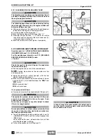
Position the vehicle on firm and flat ground.
◆
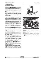
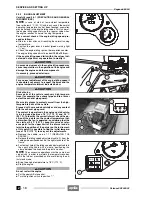
Keep the vehicle in vertical position and turn the han-
dlebar, so that the fluid contained in the tank is parallel
to the brake fluid tank cover.
◆
Make sure that the fluid level exceeds the “
MIN
” mark.
MIN
= minimum level.
If the fluid does not reach at least the “MIN” mark:
a
CAUTION
When the disc pads wear out, the level of the fluid de-
creases progressively to compensate for their wear.
◆
Check the brake pad wear, see 2.21 (CHECKING THE
BRAKE PAD WEAR) and the disc wear.
If the pads and/or the disc do not need replacing, provide
for topping up.
TOPPING UP
a
CAUTION
The brake fluid may flow out of the tank. Do not oper-
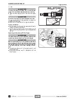
ate the front brake lever if the screws (1) (2) are loose
or, most important, if the brake fluid tank cover has
been removed.
a
CAUTION
Position a cloth under the brake reservoir, in case
some fluid should be spilled.
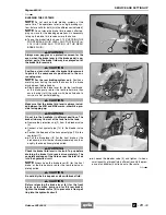
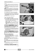
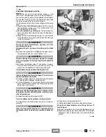
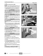
◆
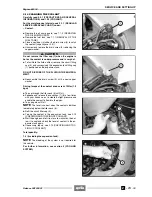
Keep the vehicle in vertical position and turn the han-
dlebar, so that the fluid contained in the tank is parallel
to the brake fluid tank cover.
◆
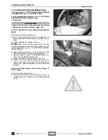
Unscrew the screw (1), using a short, cross-tip screw-
driver.
◆
Unscrew the screw (2).
a
WARNING
Avoid any prolonged exposure of the brake fluid to
the air.
The brake fluid is hygroscopic and when in contact
with the air it absorbs its humidity.
Release 00/2002-02
- 00
Summary of Contents for Pegaso 650 I.E.
Page 11: ...1 1 Pegaso 650 I E GENERAL INFORMATION 1 Release 00 2002 02 00 ...
Page 24: ...GENERAL INFORMATION 1 14 Pegaso 650 I E 1 7 2 GENERIC TOOLS Release 00 2002 02 00 ...
Page 39: ...2 1 Pegaso 650 I E 1 SERVICE AND SETTING UP 2 Release 00 2002 02 00 ...
Page 45: ...SERVICE AND SETTING UP 2 7 Pegaso 650 I E LUBRICATION CHART Release 00 2002 02 00 ...
Page 95: ...3 1 Pegaso 650 I E 1 3 ENGINE 3 Release 00 2002 02 00 ...
Page 99: ...ENGINE 3 5 Pegaso 650 I E Release 00 2002 02 00 ...
Page 113: ...4 1 Pegaso 650 I E 1 2 3 FUEL SUPPLY SYSTEM 4 Release 00 2002 02 00 ...
Page 139: ...5 1 Pegaso 650 I E 1 2 3 4 COOLING SYSTEM 5 Release 00 2002 02 00 ...
Page 149: ...6 1 Pegaso 650 I E 1 2 3 4 5 ELECTRIC SYSTEM 6 Release 00 2002 02 00 ...
Page 152: ...6 4 ELECTRIC SYSTEM Pegaso 650 I E 42 0 43 9 54 00 Release 00 2002 02 ...
Page 190: ...ELECTRIC SYSTEM 6 42 Pegaso 650 I E 7 2 2 Release 00 2002 02 00 ...
Page 193: ...7 1 Pegaso 650 I E 1 2 3 4 5 6 CHASSIS 7 Release 00 2002 02 00 ...
Page 287: ...1 2 3 4 5 6 7 8 1 Pegaso 650 I E 1 2 3 4 5 6 7 REPAIR INFORMATION 8 Release 00 2002 02 00 ...
Page 297: ...REPAIR INFORMATION 8 11 Pegaso 650 I E 8 2 3 FUEL SYSTEM PIPES Release 00 2002 02 00 ...
Page 298: ...REPAIR INFORMATION 8 12 Pegaso 650 I E 8 2 4 ENGINE OIL PIPES Release 00 2002 02 00 ...
Page 304: ...REPAIR INFORMATION 8 18 Pegaso 650 I E Release 00 2002 02 00 ...
Page 305: ...Pegaso 650 I E REPAIR INFORMATION 8 19 Release 00 2002 02 00 ...
Page 306: ...REPAIR INFORMATION 8 20 Pegaso 650 I E Release 00 2002 02 00 ...
Page 307: ...REPAIR INFORMATION 8 21 Pegaso 650 I E Release 00 2002 02 00 ...
Page 311: ... 1 Pegaso 650 I E ANALYTICAL INDEX 00 Release 00 2002 02 ...
Page 317: ...ANALYTICAL INDEX 7 Pegaso 650 I E 9 2IF 0AGE 2IF 0AGE 00 Release 00 2002 02 ...

