SERVICE AND SETTING UP
2
- 27
Pegaso 650 I.E.
",%%$).' 4(% "2!+).' 3934%-3
Carefully read 0.5.1 (PRECAUTIONS AND GENERAL
INFORMATIONS) and 1.2.6 (CLUTCH FLUID).
For the maintenance intervals, see 2.1.1 (REGULAR
SERVICE INTERVALS CHART) under:
– Braking systems;
– Brake fluid.
The air present in the hydraulic system acts as a bearing,
absorbing most of the pressure exerted by the brake
pump and reducing the effectiveness of the caliper action
during braking.
The presence of air is revealed by the “sponginess” of the
brake lever and with the reduced braking capacity.
a
WARNING
Considering the danger for both rider and vehicle, it
is absolutely essential to bleed the hydraulic circuit
once the brakes have been refitted and the braking
system restored to its normal conditions.
If the brake fluid gets in contact with the skin or the
eyes, it can cause serious irritations.
Carefully wash the parts of your body that get in con-
tact with the liquid. Consult a doctor or an oculist if
the liquid gets in contact with your eyes.
DO NOT DISPOSE OF THE FLUID IN THE ENVIRON-
MENT.
KEEP AWAY FROM CHILDREN.
a
CAUTION
Handle brake fluid with care; it may chemically alter
painted surfaces and the parts in plastic, rubber, etc.
In case any maintenance operation has to be carried
out, it is advisable to use latex gloves.
When using the brake fluid, take care not to spill it on
the plastic or painted parts, since it can damage
them.
NOTE
This vehicle is provided with disc brakes with
two, front and rear braking systems having separate hy-
draulic circuits.
The front braking system is with single disc (left side).
The rear braking system is with single disc (right side).
FRONT BRAKING SYSTEM
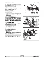
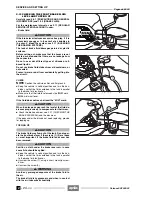
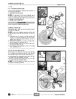
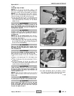
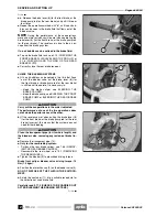
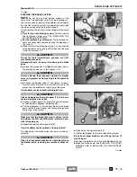
The front braking system is equipped with a single bleeder
valve (1) positioned on the front brake caliper.
REAR BRAKING SYSTEM
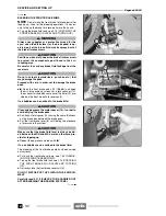
The rear braking system is equipped with a single bleeder
valve (2) positioned on the rear brake caliper.
Follow
ã
Release 00/2002-02
- 00
Summary of Contents for Pegaso 650 I.E.
Page 11: ...1 1 Pegaso 650 I E GENERAL INFORMATION 1 Release 00 2002 02 00 ...
Page 24: ...GENERAL INFORMATION 1 14 Pegaso 650 I E 1 7 2 GENERIC TOOLS Release 00 2002 02 00 ...
Page 39: ...2 1 Pegaso 650 I E 1 SERVICE AND SETTING UP 2 Release 00 2002 02 00 ...
Page 45: ...SERVICE AND SETTING UP 2 7 Pegaso 650 I E LUBRICATION CHART Release 00 2002 02 00 ...
Page 95: ...3 1 Pegaso 650 I E 1 3 ENGINE 3 Release 00 2002 02 00 ...
Page 99: ...ENGINE 3 5 Pegaso 650 I E Release 00 2002 02 00 ...
Page 113: ...4 1 Pegaso 650 I E 1 2 3 FUEL SUPPLY SYSTEM 4 Release 00 2002 02 00 ...
Page 139: ...5 1 Pegaso 650 I E 1 2 3 4 COOLING SYSTEM 5 Release 00 2002 02 00 ...
Page 149: ...6 1 Pegaso 650 I E 1 2 3 4 5 ELECTRIC SYSTEM 6 Release 00 2002 02 00 ...
Page 152: ...6 4 ELECTRIC SYSTEM Pegaso 650 I E 42 0 43 9 54 00 Release 00 2002 02 ...
Page 190: ...ELECTRIC SYSTEM 6 42 Pegaso 650 I E 7 2 2 Release 00 2002 02 00 ...
Page 193: ...7 1 Pegaso 650 I E 1 2 3 4 5 6 CHASSIS 7 Release 00 2002 02 00 ...
Page 287: ...1 2 3 4 5 6 7 8 1 Pegaso 650 I E 1 2 3 4 5 6 7 REPAIR INFORMATION 8 Release 00 2002 02 00 ...
Page 297: ...REPAIR INFORMATION 8 11 Pegaso 650 I E 8 2 3 FUEL SYSTEM PIPES Release 00 2002 02 00 ...
Page 298: ...REPAIR INFORMATION 8 12 Pegaso 650 I E 8 2 4 ENGINE OIL PIPES Release 00 2002 02 00 ...
Page 304: ...REPAIR INFORMATION 8 18 Pegaso 650 I E Release 00 2002 02 00 ...
Page 305: ...Pegaso 650 I E REPAIR INFORMATION 8 19 Release 00 2002 02 00 ...
Page 306: ...REPAIR INFORMATION 8 20 Pegaso 650 I E Release 00 2002 02 00 ...
Page 307: ...REPAIR INFORMATION 8 21 Pegaso 650 I E Release 00 2002 02 00 ...
Page 311: ... 1 Pegaso 650 I E ANALYTICAL INDEX 00 Release 00 2002 02 ...
Page 317: ...ANALYTICAL INDEX 7 Pegaso 650 I E 9 2IF 0AGE 2IF 0AGE 00 Release 00 2002 02 ...

