background image

72

use and maintenance   

Pegaso 650 I.E.

2%-/6!, /& 4(% &5%, 4!.+

Carefully  read  p.  27  (FUEL)  and  p.  55
(MAINTENANCE).

a

WARNING

Risk of fire.
Wait until the engine and the exhaust si-
lencer have completely cooled down.

Fuel  vapours  are  noxious  for  your
health.
Before proceeding, make sure that the
room in which you are working is prop-
erly ventilated. 
Do not inhale fuel vapours. 
Do  not  smoke  and  do  not  use  naked
flames. 

DO NOT DISPOSE OF FUEL IN THE EN-
VIRONMENT.

Turn the ignition switch to position “

1

”.

Remove the rider saddle, see p. 21 (UN-
LOCKING/LOCKING THE SADDLE).

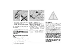
Unscrew  and  remove  the  centre  screw
(1).

Take the washer (2) and the rubber pad
(3).

~

Unscrew and remove the three screws

(4).

Disconnect  the  electric  connector  (5)
from the fuel pump.

a

CAUTION

Upon  reassembly, make  sure  that  the
electric connector (5) is correctly cou-
pled. 

a

WARNING

Position a clean cloth under the rapid
couplings (6) and (7), in order to absorb
the small quantity of fuel that will flow
out of them after disconnection.

Release  and  disconnect  the  rapid  cou-
plings (6) (7).

a

WARNING

Upon reassembly,  make  sure  that  the
rapid couplings (6) (7) are inserted cor-
rectly.
Working from the left-hand side of the
vehicle:

Move the fairing (8) moderately towards
the outside.

NOTE

Mark the two pipes (9) (10) in order

to be able to insert them in the relevant union
upon reassembly.

Withdraw  the  two  pipes  (9)  (10)  down-
wards:

– pipe (9) = fuel tank overflow;
– pipe (10) = water drainage from tank 

cap.

a

WARNING

When  reassembling,  make  sure  the
pipes are plugged in properly (9) (10).

Summary of Contents for Pegaso 650 I.E.

Page 1: ...use maintenance book PEGASO I E 650 aprilia part 8104312 ...

Page 2: ...lt in serious injury or even death aCAUTION Indicates a potential hazard which may result in minor personal injury or dam age to the vehicle NOTE The word NOTE in this manual precedes important information or instruc tions 4 2 4 The operations preceded by this symbol must be repeated also on the opposite side of the vehicle If not expressly indicated otherwise for the reassembly of the units repea...

Page 3: ...re periodical inspections The user of the vehicle in these countries must contact an aprilia Official Dealer to have the non homologated components re placed with others homologated for use in the country in question carry out the required periodical inspec tions NOTE Soon after purchasing the vehi cle write down the identification data indi cated on the SPARE PARTS IDENTIFICA TION LABEL in the ta...

Page 4: ...THE ENGINE OIL LEVEL AND TOPPING UP 59 CHANGING THE ENGINE OIL AND THE OIL FILTER 60 AIR CLEANER 62 FRONT WHEEL 64 REAR WHEEL 66 POSITIONING THE VEHICLE ON THE REAR SUPPORT STAND m 69 POSITIONING THE VEHICLE ON THE FRONT SUPPORT STAND m 69 DRIVE CHAIN 70 REMOVAL OF THE FUEL TANK 72 REMOVING THE OIL SUMP GUARD 73 REMOVING THE RIGHT AND LEFT SIDES 73 REMOVING THE DRIVE CHAIN GUARDS 74 INSTALLING THE...

Page 5: ...safe drive ...

Page 6: ...by driv ing it first in areas with low traffic and or pri vate areas The use of medicins alcohol and drugs or psychotropic substances notably increases the risk of accidents Be sure that you are in good psychophysi cal conditions and fit for driving and pay particular attention to physical weariness and drowsiness Most road accidents are caused by the driver s lack of experience NEVER lend the veh...

Page 7: ...d give due consideration to the road surface visibility and other driv ing conditions Avoid obstacles that could damage the ve hicle or make you lose control Avoid riding in the slipstream created by preceding vehicles in order to increase your speed Always drive with both hands on the han dlebars and both feet on the footrests or on the rider s footboards in the correct driving posture Avoid stan...

Page 8: ...le has been involved in an acci dent make sure that no damage has oc curred to the control levers pipes wires braking system and vital parts If necessary have the vehicle inspected by an aprilia Official Dealer who should care fully check the frame handlebars suspen sions safety parts and all the devices that you cannot check by yourself Always remember to report any malfunc tion to the technician...

Page 9: ...mance levels or alter its original characteristics Never race with other vehicles 4 Before starting always wear a correctly fastened crash helmet Make sure that it is homologated in good shape of the right size and that the visor is clean Wear protective clothing preferably in light and or reflecting colours In this way you will make yourself more visible to the other drivers thus notably reducing...

Page 10: ...gency Big fairings and windshields installed on the vehicle may produce aerodynamic forc es that affect the stability of the vehicle es pecially when riding at high speed Make sure that the equipment is well fas tened to the vehicle and not dangerous during driving Do not install electrical devices and do not modify those already existing to avoid elec trical overloads because the vehicle could su...

Page 11: ...ide with the crash helmet because they could hit people or obstacles making you lose control of the vehicle Do not carry any bag if it is not tightly se cured to the vehicle Do not carry bags which protrude too much from the luggage rack or which cover the lights horn or indicators Do not carry animals or children on the glove compartment or on the luggage rack Do not exceed the maximum load allow...

Page 12: ...ectronic unit 9 Fuse carrier 10 Passenger grab rail 11 Glove tool kit compartment 12 Rear luggage rack 13 Rear fork 14 Passenger left footrest snapping closed open 15 Centre stand m 16 Side stand 17 Rider left footrest 18 Shifting lever 19 Not provided Coolant expansion 19A Coolant expan sion 20 Rear luggage rack m 21 Left side bag m Provided as standard equipment in the countries where required ...

Page 13: ...t brake fluid tank 10 Right rear view mirror 11 Horn 12 Engine oil tank 13 Idle speed adjusting knob 14 Engine oil filter 15 Rear brake control lever 16 Rider right footrest 17 Anti theft hook for shielded cable Body Guard aprilia m 18 Rear brake pump 19 Passenger right footrest snapping closed open 20 Drive chain 21 Right side bag m supplied as standard equipment in the countries where re quired ...

Page 14: ... indicators 3 Ignition switch steering lock 2 1 4 Front brake lever 5 Throttle grip 6 Engine stop switch 2 1 7 Start push button 8 Light switch not provided for e 9 Direction indicator switch 6 10 Horn push button 11 Dimmer switch 8 7 12 High beam signalling push button 7 13 Cold start lever 0 ...

Page 15: ... temperature indicator 5 Partial kilometres odometer 6 Odometer trip control 7 Red engine oil pressure warning light 8 Blue high beam warning light 7 9 Red diagnostic warning light û 10 Amber low fuel warning light 11 Green direction indicator warning light 6 12 Green neutral indicator warning light 3425 43 4 23 ...

Page 16: ... of the engine this means that the engine oil pressure in the circuit is insufficient In this case stop the engine immediately and contact an APRILIA Official Dealer Neutral indicator warning light Comes on when the gear is in neutral Diagnostic warning light û It comes on whenever the ignition switch is positioned on 2 and goes out a few seconds after the engine start Do not carry out any operati...

Page 17: ... maximum allowed temperature is exceeded red area of the scale the engine may be seriously damaged If the pointer gets near the red area stop the engine wait until the cooling fan is disconnected and check the coolant level see p 34 COOLANT If the pointer reaches the red area stop the vehicle and let the engine idle for approximately two minutes thus permitting the regular circulation of the coola...

Page 18: ...le if it is in po sition 8 the low beam comes on 3 DIMMER SWITCH 8 7 e When it is in position 8 the parking lights the dashboard light and the low beam are always on When it is in position 7 the high beam comes on 4 HIGH BEAM SIGNALLING PUSH BUTTON 7 It makes it possible to use the high beam for signalling to forthcoming vehicles while overtaking and in case of peril and or emergency The high beam...

Page 19: ...ped engine and ignition switch in position 2 the battery may discharge When the vehicle has come to rest after stopping the en gine move the ignition switch to position 1 2 LIGHT SWITCH not provided for e When the light switch is in position the lights are off when the switch is in position the parking lights and the dash board light are on when the switch is in position the parking lights the das...

Page 20: ...supplied together with the vehicle one spare key NOTE Do not keep the spare key on the vehicle Position Function Key removal Steering lock The steer ing is locked It is neither pos sible to start the engine nor to switch on the lights It is possible to remove the key Neither the engine nor the lights can be switched on It is possible to remove the key The engine and the lights can be switched on I...

Page 21: ...thdraw the key 1 58 29 15 0 4 5 4 3 Position the vehicle on the stand see p 52 POSITIONING THE VEHICLE ON THE STAND Insert the key 1 in the saddle lock 2 Turn the key 1 clockwise and raise and remove the saddle NOTE Before lowering and locking the saddle make sure that you have not left the key in the glove tool kit compartment To lock the saddle Position the tangs 3 in the seat lower and press th...

Page 22: ...r spark plug 8 socket spanner rod 9 double ended cross cut headed screw driver 10 tool case 11 Maximum allowed weight 1 5 kg 4 4 4 The anti theft hook 12 is positioned on the right side of the vehicle near the rider footboard To prevent the vehicle from being stolen it is advisable to secure it with the shielded cable Body Guard aprilia m 13 avail able at the aprilia Official Dealers aWARNING Do n...

Page 23: ... centre stand m supplied as standard equipment in the countries where re quired Tool Operations Support pins 1 for the rear support stand see p 69 PO SITIONINGTHE VEHICLE ON THE REAR SUPPORT STAND m Positioning of the vehicle on the rear stand Rear support stand 2 see p 69 POSITIONING THE VEHI CLE ON THE REAR SUP PORT STAND m Rear wheel di sassembly Drive chain adjustment Front support stand 3 see...

Page 24: ...rs to one unit only but is valid for both To open the side bag proceed as fol lows Position the vehicle on the stand see p 52 POSITIONING THE VEHICLE ON THE STAND Introduce the key 1 in the lock Turn the key 1 anticlockwise Extract the key 1 and insert it in the oth er lock Turn the key 1 anticlockwise Lift the two parts of the lock 2 Open the case 3 Two keys are supplied together with the vehicle...

Page 25: ... seats 5 on the bag support Two keys are supplied together with the vehicle one spare key NOTE Do not keep the spare key on the vehicle aCAUTION Handle the plastic and painted compo nents with care to avoid scraping or damaging them aWARNING Upon reassembly make sure that the bag is properly anchored to its support Upper part perfect fitting of the bag coupling pins in the coupling seats pro vided...

Page 26: ...clockwise Remove the handle 2 Lift the lock 3 Release the upper part 4 of the lock 3 from the case 5 Lift the upper part of the case to open it 5 NOTE The case can contain two CRASH helmets Two keys are supplied together with the vehicle one spare key NOTE Do not keep the spare key on the vehicle aWARNING Do not load the rear case excessively Maximum allowed weight 5 kg To remove the rear case pro...

Page 27: ...could catch fire when getting in contact with the red hot sur faces of the engine In case some fuel has accidentally been spilt make sure that the area has com pletely dried and before starting the ve hicle verify that there is no fuel inside the fuel filler neck Since petrol expands under the heat of the sun and due to the effects of sun ra diation never fill the tank to the brim aWARNING Screw t...

Page 28: ...other similar items make sure that they are perfectly clean aWARNING Do not fill the tank completely the max imum fuel level must remain below the lower edge of the filler neck see figure aCAUTION During the refilling operations be care ful to avoid damaging the inner parts of the tank with the fuel pump Refuel After refuelling NOTE The cap can be closed only when the key 2 is inserted With insert...

Page 29: ...iscs are nei ther oily nor greasy especially after maintenance or checking operations Check that the brake cables are neither twisted nor worn out Prevent water or dust from accidentally getting into the circuit In case maintenance operations are to be performed on the hydraulic circuit it is advisable to use latex gloves If the brake fluid gets in contact with the skin or the eyes it can cause se...

Page 30: ...llowing information refers to a single braking system but is valid for both When the disc pads wear out the level of the fluid decreases to automatically com pensate for their wear The front brake fluid tank is positioned on the right part of the handlebar near the front brake lever coupling The rear brake reservoir is positioned on the right side of the vehicle near the rear brake control lever N...

Page 31: ...TOPPING UP Carefully read p 29 BRAKE FLUID recommendations aCAUTION The brake fluid may flow out of the tank Do not operate the front brake lever if the screws 1 and 2 are loose or most important if the brake fluid tank cover has been removed aCAUTION Position a cloth under the brake reser voir in case some fluid should be spilled Keep the vehicle in vertical position and turn the handlebar so tha...

Page 32: ...round Top up the reservoir 6 by adding brake fluid see p 104 LUBRICANT CHART until reaching the correct level aCAUTION Do not exceed the MAX level while topping up It is advisable to top up until reaching the MAX level only with new pads Do not reach the MAX level with worn out pads since this will cause a fluid outflow when the pads are changed Put back the gasket 4 in its seat cor rectly Put bac...

Page 33: ...the air The brake fluid is hygroscopic and when in contact with the air it absorbs its humidity Leave the brake fluid tank open ONLY for the time necessary for topping up Unscrew and remove the plug 1 Remove the gasket 2 aCAUTION In order not to spill the brake fluid while topping up keep the fluid in the tank parallel to the tank rim in horizontal po sition Do not put additives or other subtances...

Page 34: ... the engine it may catch fire and send out invisible flames In case any maintenance operation should be required it is advisable to use latex gloves aCAUTION Have the pads changed by your APRILIA Official Dealer The coolant is composed of 50 water and 50 antifreeze This mixture is ideal for most running tem peratures and ensures good protection against corrosion It is advisable to keep the same mi...

Page 35: ...G The coolant is noxious do not swallow it if the coolant gets in contact with the skin or the eyes it can cause serious ir ritations Do not use your fingers or any other ob ject to check if there is enough coolant aCAUTION Do not put additives or other subtances into the fluid If you use a funnel or other similar items make sure that they are perfectly clean Top up the expansion tank by adding co...

Page 36: ... case of sudden braking the tyres could even come off the rims Further the vehicle could skid while turning aWARNING Check the surface and the wear of the tyres since tyres in bad conditions can impair both the grip and the controlla bility of the vehicle Some types of tyres homologated for this vehicle are provided with wear indi cators There are several kinds of wear indica tors For more informa...

Page 37: ...er and take it to the filling station where you usually buy it or to an oil salvage center In case any maintenance operation should be required it is advisable to use latex gloves aCAUTION If the engine oil pressure warning light comes on during the normal oper ation of the engine this means that the engine oil pressure in the circuit is in sufficient In this case check the engine oil level see p ...

Page 38: ...e lock nut 2 Rotate the adjuster 3 until the idle stroke of the clutch lever is about 10 mm Tighten the lock nut 2 and check the adjustment again Start the engine see p 44 STARTING Pull the clutch control lever completely and engage the 1st gear Make sure that the engine does not stop that the vehicle does not tend to move for ward or that the clutch does not slip during the acceleration phase or ...

Page 39: ...mp control rod 4 and the pump piston aCAUTION Make sure that there is a certain idle stroke in the movement of the lever 5 to prevent the brake from remaining ap plied and the consequent untimely wear of the braking elements Lever 5 idle stroke 4 mm measured at the lever end Lock the pump control rod 4 by means of the lock nut 3 aCAUTION After the adjustment make sure that the wheel rotates freely...

Page 40: ...er than for purposes of maintenance repair or replacement of any device or element of design incorpo rated into any new vehicle for the pur pose of noise control prior to its sale or delivery to the ultimate purchaser or while it is in use the use of the vehicle after such device or element of design has been removed or rendered inoperative by any person Check the exhaust silencer and the silencer...

Page 41: ... on and off the weight of the vehicle may cause an unbalance and the consequent loss of equilibrium and the ve hicle may fall or overturn NOTE The rider must always be the first person to get on the vehicle and the last to get off and it is the rider who controls the balance and stability of the vehicle when the passenger gets on and off When getting on and off the vehicle the passenger must make ...

Page 42: ...E If it is impossible for you to place both feet on the ground place the right foot on the ground in case of unbalance the left side of the vehicle is prevented from falling over by the side stand and keep the left foot ready to rest on the ground Place both feet on the ground keeping the vehicle in balance in riding position Instruct the passenger how to safely get off the vehicle aCAUTION Risk o...

Page 43: ...clutch must work without jerking and or slipping 38 CLUTCH Steering Make sure that the steering rotates smoothly without any clearance or slackening Side stand and centre stand m supplied as standard equipment in the countries where required Make sure that it operates correctly Make sure that when the stand is let up or down there is no friction and that the spring tension brings it back to its no...

Page 44: ...h the side stand up it is possible to start the engine either in neutral gear or with en gaged gears and pulled in clutch lever Get on the vehicle in riding position see p 40 GETTING ON AND OFF THE VE HICLE Make sure that the stand is completely up Not provided for e Make sure that the light switch 1 is in position Make sure that the dimmer switch 2 is in position 8 Move the engine stop switch 3 t...

Page 45: ...n the engine is running since you may damage the starter If the engine oil pressure warning light 5 remains on or if it comes on during the normal operation of the en gine this means that the oil pressure in the circuit is insufficient In this case stop the engine immediate ly and contact an APRILIA Official Dealer Keep at least one brake lever pulled and do not accelerate until you start aCAUTION...

Page 46: ...n wards Insist for at least ten seconds with the start push button 11 pressed and at the same time moderately rotate the throttle grip 13 If the engine starts Release the start push button 11 and the throttle grip 13 Rotate the cold start lever 0 12 up wards If the idling is unstable twist the throttle grip 13 slightly and frequently If the engine does not start Wait a few seconds and repeat the c...

Page 47: ...eet on the footrests NEVER RIDE IN ANY POSITION OTHER THAN THOSE INDICATED aWARNING If you drive with a passenger instruct him her so that he she does not create problems during manouvres Before leaving make sure that the stand is completely up To leave Start the engine see p 44 STARTING Adjust the inclination of the rear view mirrors correctly see p 83 REAR VIEW MIRRORS aCAUTION With the vehicle ...

Page 48: ...er ride the vehicle at too low rpm Release the throttle grip 2 Pos A pull the clutch lever 3 and lift the shifting le ver 4 Release the clutch lever 3 and accelerate Repeat the last two operations and shift up aCAUTION If the engine oil pressure warning light 5 comes on during the normal operation of the engine this means that the engine oil pressure in the circuit is insufficient In this case sto...

Page 49: ...engaged gears and pulled clutch lever for the shortest possible time aWARNING Avoid opening and closing the throttle grip repeatedly and continuously so that you do not accidentally lose control of the vehicle If you have to brake close the throttle and put on both brakes in order to obtain uniform decel eration properly exerting pressure on the braking parts By putting on the front brake only or ...

Page 50: ...i of running in you can expect the best performance levels from the vehicle Keep to the following indications Do not open the throttle completely if the speed is low both during and after the running in During the first 500 km 312 mi put on the brakes with caution avoiding sharp and prolonged brakings This ensures a correct bedding in of the pads on the brake disc During the first 500 km 312 mi ne...

Page 51: ... prevent it from falling down Neither lean the vehicle against walls nor lay it on the ground Make sure that the vehicle and especial ly its red hot parts do not represent a danger for persons and children Do not leave the vehicle unattended when the engine is on or the key is inserted into the ignition switch Do not get too near the cooling fan even if it is not in operation since it may start an...

Page 52: ...e side stand while seated astride the vehicle see p 40 GETTING ON AND OFF THE VEHICLE If any manoeuvre for example moving the vehicle required the lifting of the stand to place the vehicle on the stand again pro ceed as follows aWARNING Make sure that the parking surface is free from obstacles firm and flat Choose a suitable parking area see p 51 PARKING Grasp the left grip 1 and the handle 2 Pres...

Page 53: ... falling down or overturning in case of unbalance NOTE Do not let the side stand touch the ground Keep the vehicle in vertical po sition Press the side stand with your right foot and extend it completely 3 Push down the lever 4 Pos A of the centre stand and make it rest on the ground aCAUTION Proceed with care The positioning of the vehicle on the centre stand may be difficult since the vehicle is...

Page 54: ...ce When possible use an additional anti theft device Make sure that all documents are in order and the road tax has been paid Write down your personal data and tele phone number in this page to facilitate the identification of the owner in case of finding after theft SURNAME NAME ADDRESS TELEPHONE NO NOTE Very often stolen vehicles are identified thanks to the data written in the use maintenance m...

Page 55: ...d any mechanical piece or other parts of the vehicle with your mouth the components are not edible and some of them are noxious or even toxic aCAUTION If not expressly indicated otherwise for the reassembly of the units repeat the disassembly operations in reverse or der In case any maintenance operation should be required it is advisable to use latex gloves Routine maintenance operations can usu ...

Page 56: ...0 km 625 mi Every 6000 km 3750 mi or 12 months Every 12000 km 7500 mi or 24 months Battery Terminal fastening Electrolyte level Spark plug Air cleaner Engine oil filter Engine oil filter on oil tank Fork Light operation direction Light system Safety switches Brake fluid Coolant Engine oil Side bag coupling pins Tyres every 1000 km 625 mi Tyre pressure every 1000 km 625 mi Engine idling rpm and CO ...

Page 57: ...rminal fastening Carburation CO adjustment Timing chain Transmission cables and controls Wheel centering Rear suspension linkage bearings Steering bearings and steering clearance Wheel bearings Brake discs Fuel pump filter every 15000 km 9375 mi General running of the vehicle Clutch clearance Adjusting the valve clearance Braking systems Cooling system Brake fluid every 2 years Coolant Fork oil ev...

Page 58: ... the com ponents positioned near the joint CLICK CLAMPS For the removal it is sufficient to use simple pliers while for the installation it is neces sary to use a special tool see below Before removing a clamp prepare the ma terial necessary for the correct reassembly NOTE Have the appropriate special tool m to hand clamp installation pliers see p 23 SPE CIAL TOOLS m aCAUTION Upon installation rep...

Page 59: ...NG Keep the vehicle in vertical position with the two wheels resting on the ground Insert the plug dipstick 1 completely in the inlet hole 2 without screwing it Extract the plug dipstick 1 again and read the oil level on the dipstick MAX maximum level MIN minimum level The difference between MAX and MIN amounts to approximately 300 cm The level is correct when the oil almost reaches the MAX mark a...

Page 60: ...t According to the correct procedure it is advisable to carry out the check after a trip of after covering approximately 15 km 10 mi on a road outside town this is suffi cient for the engine oil to reach the operat ing temperature Stop the engine see p 51 STOPPING Keep the vehicle in vertical position with the two wheels resting on the ground Remove the oil sump guard see p 73 REMOVING THE OIL SUM...

Page 61: ...t have already been used Spread an oil film on the sealing ring 8 of the new engine oil filter Fit the new engine oil filter Put back the cover 6 screw and tighten the two screws 5 CLEANING THE ENGINE OIL FILTER ON THE TANK Clean the engine oil filter 9 on the tank after the first 1000 km 625 mi and suc cessively every 12000 km 7500 mi or every two engine oil changes Remove the fuel tank see p 72 ...

Page 62: ... SUMP GUARD Start the engine see p 44 STARTING and let it idle for about one minute in or der to ensure the filling up of the engine oil circuit Check the oil level and top up if neces sary see p 59 CHECKING THE EN GINE OIL LEVEL AND TOPPING UP 2 2 Check the air cleaner every 6000 km 3750 mi or 12 months change it every 12000 km 7500 mi or more frequently if the vehicle is used on dusty or wet roa...

Page 63: ...tering element PARTIAL CLEANING aCAUTION Do not press or strike the metal net of the air cleaner 3 Do not use screwdrivers or alike Seize the air cleaner 3 vertically and strike it more than once on a clean sur face If necessary clean the air cleaner 3 with a compressed air jet directing it from the inside towards the outside of the filter aCAUTION When cleaning the filtering element make sure tha...

Page 64: ...1 under the tyre in such a way as to keep the wheel in its position after loosening it aCAUTION Make sure that the vehicle is stable Partially unscrew the two wheel pin clamp screws 2 right side Unscrew the wheel pin 3 completely NOTE To facilitate the extraction of the wheel pin slightly raise the wheel Support the front wheel and manually withdraw the wheel pin 3 Take the left spacer ring 4 left...

Page 65: ...ving torque 3 80 Nm 8 kgm Remove the support 1 that upon disas sembly was put under the tyre aWARNING Due to the weight and dimensions of the vehicle the following operation must be performed by two persons NOTE Weight without driver ready for starting 200 kg Remove the front support stand see p 69 POSITIONING THE VEHICLE ON THE FRONT SUPPORT STAND m Remove the rear support stand see p 69 POSITION...

Page 66: ...im and change it if it is damaged DISASSEMBLY Position the vehicle on the appropriate rear support stand see p 69 POSI TIONING THE VEHICLE ON THE REAR SUPPORT STAND m Put a support 1 under the tyre in such a way as to keep the wheel in its position after loosening it Lock the rotation of the wheel pin 2 with the appropriate key Unscrew and remove the nut 3 and re trieve the washer 4 Wheel nut 3 dr...

Page 67: ...ecessary if the wheel is in the normal running position vertical or in horizontal position with the rear sprocket facing up wards and in both cases secured against overturning NOTE Do not unscrew the six nuts 12 The whole final drive unit must be with drawn from the flexible coupling holder Withdraw the final transmission unit 10 keeping it parallel to the wheel axis Remove the four flexible coupl...

Page 68: ...ackwards until its cen tral hole and the holes on the rear fork are aligned Rotate the support plate 8 complete with brake caliper 9 and with fulcrum on the stop pin until it is aligned with the holes Insert the washer 5 in the wheel pin 2 Introduce the wheel pin 2 completely from the left side NOTE Make sure that the wheel pin 2 is completely inserted Position the washer 4 and tighten the wheel n...

Page 69: ... 3 and make them hit against the rear fork Tighten the two knobs 1 Push the stand forward 7 until the sup port pin 3 rests on the right side against the rear fastening plate of the lower chain guard NOTE Have someone help you keep the vehicle in vertical position with the two wheels on the ground Rest one foot on the rear part of the stand 7 Push the stand 7 downwards until it reaches the end of i...

Page 70: ... VEHICLE ON THE REAR SUPPORT STAND m Position the shifting lever in neutral Make sure that the vertical oscillation in an intermediate point between pinion and crown in the lower part of the chain is included between 35 45 mm Rotate the wheel manually in such a way as to check the vertical oscillation of the chain even in other positions the slack must be constant in all the wheel rotation phases ...

Page 71: ...kets and chain aCAUTION Lubricate the chain frequently espe cially if there are dry or rusty parts The crushed or seized links must be lu bricated and made work again If this is not possible contact an APRIL IA Official Dealer who will provide for changing the chain Finally check the wear of the rear fork protection shoe CLEANING AND LUBRICATION aCAUTION The drive chain is provided with O rings am...

Page 72: ...e the three screws 4 Disconnect the electric connector 5 from the fuel pump aCAUTION Upon reassembly make sure that the electric connector 5 is correctly cou pled aWARNING Position a clean cloth under the rapid couplings 6 and 7 in order to absorb the small quantity of fuel that will flow out of them after disconnection Release and disconnect the rapid cou plings 6 7 aWARNING Upon reassembly make ...

Page 73: ...IONING THE VEHICLE ON THE STAND Unscrew and remove the four screws 1 aCAUTION Handle the plastic and painted compo nents with care to avoid scraping or damaging them Remove the oil sump guard 2 NOTE If the deadening material inside the oil sump guard 2 is deteriorated con tact an aprilia Official Dealer to have it changed 2 6 4 2 4 4 3 3 Carefully read 55 MAINTENANCE aWARNING Wait until the engine...

Page 74: ...e lower protection element 5 34 4 3 3500 243 m SUPPLIED AS STANDARD EQUIPMENT IN THE COUNTRIES WHERE REQUIRED NOTE If also the rear case supports must be installed beside the side bag sup ports it is necessary to install the former first see p 76 INSTALLING THE REAR CASE SUPPORTS m supplied as stand ard equipment in the countries where re quired Carefully read 55 MAINTENANCE The following parts ar...

Page 75: ...er ring 7 Insert the screws 5 6 and screw them manually Tighten the screws 5 6 and the nut 10 without applying the torque pre scribed Tighten the screw 1 and the screw 2 applying the torque prescribed Driving torque of screws 1 2 25 Nm 2 5 kgm Unscrew and remove the screws 5 6 and the nut 10 Remove the bag support 11 Put back the side cover see p 73 REMOVING THE RIGHT AND LEFT SIDES aCAUTION Handl...

Page 76: ...d the washer C will be reused in the following operations çPosition the rear coupling 7 çInsert the screw B with the relevant washer C and screw it manually Position the spacer ring 6 Position the case side support 8 Insert the screws 1 4 and screw them manually Position the plate 9 on the two side supports 8 Insert one of the screws 2 with the relevant washer 3 Working on the lower side position ...

Page 77: ...00 km 7500 mi With pulled front brake lever press the handlebar repeatedly thrusting the fork downwards The stroke must be gentle and there must be no trace of oil on the rods Check the fastening of all the compo nents and the functionality of the front and rear suspension joints aCAUTION If you notice irregularities in the opera tion or if the help of a qualified technician is necessary contact y...

Page 78: ...y 70 kg If your weight and needs are different for example in case of ride with passenger and full load it is advisable to contact an aprilia Official Dealer According to the conditions of use of the vehicle it is possible to adjust the hydraulic braking with extended shock absorber by adjusting the screw 1 for the adjustment keep to the following indications Uneven or irregular road surface HARD ...

Page 79: ... completely clockwise HARD Spring preload knob 2 starting from the soft adjustment position anticlockwise rotate the knob clockwise giving it a full turn 9 clicks turn completely anticlockwise turn completely clockwise 2 2 3530 3 7 4 9 2 5 02 534 4 m With this type of suspension it is possible to adjust the spring preload and the hy draulic braking with extended shock ab sorber aCAUTION Adjust the...

Page 80: ... STAND Carry out a visual check between the disc and the pads proceeding from below on the front part for the front brake caliper 1 from above on the rear part for the rear brake calipers 2 aCAUTION The excessive wear of the friction mate rial would cause the contact of the pad metal support with the disc with conse quent metallic noise and production of sparks from the caliper braking effi ciency...

Page 81: ...cial Dealer An excessive increase in the engine idling rpm may cause irregularities in the operation of the engine and damage the engine itself and other components It is advisable to change the setting only when it is really necessary if when the throttle grip is released the engine stops or keeps running at higher rpm than prescribed and it is impossi ble to reach an APRILIA Official Dealer Only...

Page 82: ...tion of the handlebar does not mod ify the engine idling rpm and that the throttle grip returns smoothly and auto matically to its original position after being released 534 4 34 24 42 Carefully read p 55 MAINTENANCE Have the accelerator control cables checked by an aprilia Official Dealer after the first 1000 km 625 mi and successively every 6000 km 3750 mi The idle stroke of the cold start contr...

Page 83: ...ON THE STAND Raise the protection element 1 Loosen and remove the stop nut 2 aCAUTION Upon reassembly before tightening the lock nut 2 make sure that the rear view mirror support rod is directed in such a way as to be aligned with the handlebar Withdraw the entire rear view mirror unit 3 upwards and remove it Repeat these operations to remove the other rear view mirror ADJUSTMENT OF THE REAR VIEW ...

Page 84: ... as follows Remove the cap 1 of the spark plug 2 Remove any trace of dirt from the spark plug base Introduce the special spanner provided in the tool kit on the spark plug Unscrew the spark plug and extract it from its seat taking care to prevent dust or other substances from getting inside the cylinder For the check and cleaning Key centre electrode 3 insulating 4 side electrode 5 Make sure that ...

Page 85: ...Make sure that the washer 7 is in good conditions For the installation With the washer on 7 screw the spark plug by hand in order not to damage the thread Tighten the spark plug by means of the spanner you will find in the tool kit giving it half a turn to compress the washer Spark plug driving torque 20 Nm 2 0 kgm aCAUTION The spark plug must be well tightened otherwise the engine may overheat an...

Page 86: ...de stand must rotate freely if nec essary grease the joint see p 104 LU BRICANT CHART The side stand 1 is provided with a safety switch 4 that has the function to prevent or interrupt the operation of the engine with the gears on and the side stand 1 down To check the proper functioning of the safety switch 4 proceed as follows Start the engine see p 44 STARTING With released throttle grip 5 Pos A...

Page 87: ...e is accidentally swal lowed drink a lot of water or milk then continue drinking milk of magnesia or vegetable oil and consult a doctor with out delay The battery gives off explosive gases keep it away from flames sparks ciga rettes and any other source of heat During the recharging or the use make sure that the room is properly ventilated and avoid inhaling the gases released during the rechargin...

Page 88: ...ding only distilled water Put back the left cover see p 73 RE MOVING THE RIGHT AND LEFT SIDES 4 4 2 3 Carefully read p 87 BATTERY Make sure that the ignition switch is in po sition 1 Remove the left cover see p 73 RE MOVING THE RIGHT AND LEFT SIDES Remove the red protection element 1 Make sure that the cable terminals 2 and the battery terminals 3 are in good conditions and not corroded or covered...

Page 89: ...ve terminal Move the positive cable 7 sidewards aCAUTION Do not force the electric cables Withdraw the breather pipe 8 Grasp the battery 9 firmly and remove it from its compartment by bending it to wards the outside and lifting it aWARNING Once it has been removed the battery must be stored in a safe place and kept away from children Position the battery on a flat surface in a cool and dry place P...

Page 90: ...uce gas for a short lapse of time 34 4 44 29 Carefully read p 87 BATTERY Make sure that the ignition switch is in position 1 Remove the left cover see p 73 RE MOVING THE RIGHT AND LEFT SIDES NOTE The battery 1 must be posi tioned in its compartment with the termi nals directed towards the outside part of the vehicle Put the battery 1 in its compartment aWARNING Upon reassembly connect first the po...

Page 91: ...arge it completely with a trickle charge see p 90 RECHARGING THE BATTERY If the battery remains on the vehicle dis connect the cables from the terminals 4 37 4 3 Carefully read p 55 MAINTENANCE The vehicle is provided with four switches 1 Stoplight switch on the rear brake con trol lever 2 Stoplight switch on the front brake con trol lever 3 Safety switch on the side stand 4 Switch on the clutch c...

Page 92: ...o check the fuses For the check proceed as follows Turn the ignition switch to position 1 to avoid any accidental short circuit Remove the rider saddle see p 21 UN LOCKING LOCKING THE SADDLE Extract the fuses one by one and check if the filament 1 is broken Before replacing a fuse try to find out the cause of the trouble if possible Replace the damaged fuse with a new one having the same amperage ...

Page 93: ...ontal line of the headlight about 9 10th of the total height To adjust the headlight beam Position the vehicle on the stand see p 52 POSITIONING THE VEHICLE ON THE STAND Working on the lower side of the front part of the fairing act on the appropriate screw 1 with the spanner 8 mm pro vided in the tool kit BY ROTATING IT CLOCKWISE you set the beam upwards BY ROTATING IT ANTICLOCKWISE you set the b...

Page 94: ...he bulb since these may cause its overheating and consequent breakage If you touch the bulb with bare hands remove any fingerprint with alcohol in order to avoid any damage DO NOT FORCE THE ELECTRIC CA BLES NOTE Before changing a bulb check the fuses see p 92 CHANGING THE FUSES 4 4 5 3 Carefully read p 94 BULBS The headlight contains one high beam bulb 1 left side one parking light bulb 2 lower on...

Page 95: ...t pull the electric wires Grasp the parking light bulb socket 9 pull it and remove it from its seat Withdraw the bulb 2 and replace it with one of the same type LOW BEAM BULB HIGH BEAM Move the protection element 10 with your hands aCAUTION To extract the bulb electric connector do not pull its electric wires Grasp the bulb electric connector 11 pull it and disconnect it from the bulb 3 Rotate the...

Page 96: ...same type 4 2 2 2 4 4 2 5 3 Carefully read p 94 BULBS Position the vehicle on the stand see p 52 POSITIONING THE VEHICLE ON THE STAND Unscrew and remove the screw 4 aCAUTION While removing the protection screen proceed carefully in order not to break the cog Remove the protection screen 5 aCAUTION Upon reassembly correctly position the protection screen in its seat Tighten the screw 4 moderately a...

Page 97: ...refully without ex erting too much pressure in order to avoid damaging the protection screen Press the bulb 1 slightly and rotate it anticlockwise Extract the bulb 1 from its seat aCAUTION Insert the bulb in the bulb socket mak ing the two bulb pins coincide with the relevant guides on the socket Correctly install a new bulb of the same type 4 5 2 0 4 5 Carefully read p 94 BULBS To change proceed ...

Page 98: ...mid climates Particular conditions use of salt and anti ice chemical products on the roads during the winter Avoid leaving deposits of industrial and polluting powders tar spots dead in sects bird droppings etc on the body Avoid parking the vehicle under trees since in some seasons residues resins fruits or leaves fall down which contain substances that may damage the paint aWARNING After the vehi...

Page 99: ...y of wa ter Polish with silicone wax only after hav ing carefully washed the vehicle Do not use polishing pastes on matt paints Do not wash the vehicle under the sun especially during the summer when the body is still warm since if the shampoo dries before being rinsed away it can damage the paint Do not use liquids at a temperature ex ceeding 40 C to clean the plastic com ponents of the vehicle a...

Page 100: ...osition the vehicle on the front m and rear m support stands so that both tyre are raised from the ground Set the vehicle on the relevant front sup port stand see 69 POSITIONING THE VEHICLE ON THE FRONT SUPPORT STAND m Put a plastic bag on each exhaust tail pipe and bind it around it in order to pre vent moisture from getting into the tail pipe Cover the vehicle avoiding the use of plastic or wate...

Page 101: ...5 1 Starting electric Engine idling rpm 1300 100 rpm Clutch multidisc in oil bath with control on the left side of the handlebar Lubrication system dry pan with separate oil tank Air cleaner with dry filter cartridge Cooling liquid cooled TRANSMISSION Type mechanical 5 gears with foot control on the left side of the engine CAPACITY Fuel reserve included 21 L Fuel reserve 5 L Engine oil oil change ...

Page 102: ...le and saddle pillar Steering inclination angle 28 Fore stroke 109 mm SUSPENSIONS Front upside down telescopic adjustable fork with hydraulic operation rod Ø 45 mm Stroke 170 mm Rear oscillating rear fork with differentiated profile arms and hydraulic adjustable mono shock absorber Wheel stroke 165 mm BRAKES Front disc brake Ø 300 mm with hydraulic transmission Rear disc brake Ø 240 mm with hydrau...

Page 103: ...Standard NGK R DR8EB Spark plug gap 0 6 0 7 mm Resistance 5 kΩ ELECTRIC SYSTEM Battery 12 V 12 Ah Fuses 7 5 A 15 A 20 A Generator with permanent magnet 12 V 270 W BULBS Low beam bulb high beam 12 V 55 60 W High beam 12 V 60 W Front parking light 12 V 3 W Direction indicators 12 V 10 W Rear parking lights Stoplight 12 V 5 21 W Number plate light 12 V 3 W Revolution counter 12 V 2 W Speedometer 12 V...

Page 104: ...ORK 20W 33 of the volume SAE 15W 0F A 5W 33 of the volume 0F A 20W 67 of the volume or FORK 5W 33 of the volume FORK 20W 67 of the volume Bearings and other lubrication points recommended 0AUTOGREASE MP or GREASE 30 As an alternative to the recommended product use high quality grease for rolling bearings working temperature range 30 C 140 C dripping point 150 C 230 C high protection against corros...

Page 105: ...105 4 3 2 5 30 2 0 243 9 use and maintenance Pegaso 650 I E ...

Page 106: ...106 use and maintenance Pegaso 650 I E MPORTERS ...

Page 107: ......

Page 108: ...108 use and maintenance Pegaso 650 I E 7 2 2 0EGASO ...

Page 109: ... unit 27 Rear light 28 Number plate bulb 29 Rear right direction indicator 30 Front stoplight switch 31 Rear stoplight switch 32 Thermal switch cooling electrofan 33 Cooling electrofan 34 Injection relay 35 Start relay 36 Starter 37 Battery 38 Voltage regulator 39 Fuses 40 Generator 41 Pick up 42 Fuel pump 43 Low fuel sensor 44 Injector 2 45 Injector 1 46 Throttle valve position sensor 47 Coolant ...

Page 110: ...110 4 3 2 5 30 2 0 243 9 use and maintenance Pegaso 650 I E ...

Page 111: ...111 4 3 2 5 30 2 0 243 9 use and maintenance Pegaso 650 I E ...

Page 112: ...ia s p a wishes to thank its customers for the purchase of this vehicle Do not dispose of oil fuel polluting substances and components in the envi ronment Do not keep the engine running if it isn t necessary Avoid disturbing noises Respect nature ...

Reviews: