5
- 7
SISTEMA DE REFRIGERACIÓN
COOLING SYSTEM
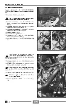
5.2 DESMONTAJE RADIADOR
Lea con cuidado 1.2.5 (LÍQUIDO REFRIGERANTE) y
1.4 (PRECAUCIONES E INFORMACIONES GENERA-
LES).
◆
Coloque el vehículo sobre el caballete.
Deje enfriar el motor hasta que el mismo al-
cance la temperatura ambiente.
◆
Descargue del todo el circuito de refrigeración, véase
2.15 (SUBSTITUCIÓN DEL LÍQUIDO REFRIGERAN-
TE).
◆
Saque el depósito del combustible, véase 7.1.1 (DES-
MONTAJE DEPOSITO COMBUSTIBLE).
◆
Extraiga el carenado delantero, véase 7.1.14 (DES-
MONTAJE CARENADO DELANTERO).
◆
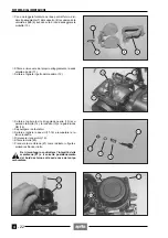
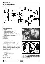
Destornille y saque los tornillos (1).
◆
Extraiga el encauzador aire (2).
◆
Saque el elemento de protección (3) y desconecte el
terminal eléctrico (4) del termistor (5).
◆
Desconecte el conector eléctrico (6) del electroventila-
dor (7).
Suelte todos los cables y los tubos de sus co-
rrespondientes abrazaderas de bloqueo.
Prepare, luego, un número igual de abrazade-
ras que habrá que utilizar durante la instalación.
◆
Desconecte los dos conectores eléctricos (8-9) del ter-
mointerruptor (10).
◆
Ladee la abrazadera (11) y saque de la boca el tubo
de compensación (12).
Prepare un número igual de abrazaderas de
destornillador que habrá que sustituir a las
originales (de tipo especial sin tornillo).
◆
Corte la cabeza de las abrazaderas (13) y (14).
Durante la instalación hay que sustituir las
abrazaderas (13) y (14) con otras nuevas.
◆
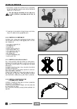
Saque de los enganches radiador los dos manguitos
(15) y (16).
a
a
c
c
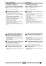
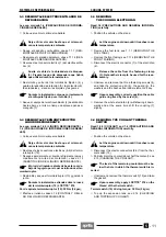
5.2 REMOVING THE RADIATOR
Read 1.2.5 (COOLANT) and 1.4 (PRECAUTIONS AND
GENERAL INFORMATION) carefully.
◆
Position the vehicle on the stand.
Let the engine cool down until it reaches room
temperature.
◆
Drain the cooling circuit completely, see 2.15
(CHANGING THE COOLANT).
◆
Remove the fuel tank, see 7.1.1 (REMOVING THE
FUEL TANK).
◆
Remove the front fairing, see 7.1.14 (REMOVING THE
FRONT FAIRING).
◆
Unscrew and remove the screws (1).
◆
Remove the air conveyor (2).
◆
Withdraw the protection element (3) and disconnect
the electric terminal (4) from the thermistor (5).
◆
Disconnect the electric connector (6) of the electrofan
(7).
Release all the cables and pipes from the fas-
tening clamps positioned along them. Get oth-
er clamps to be used for the reassembly.
◆
Disconnect the two electric connectors (8-9) from the
thermal switch (10).
◆
Move the pipe clamp (11) and withdraw the coolant
compensating pipe (12) through the filler neck.
Get screwdriver-type pipe clamps, to replace
the original ones (special type without screw).
◆
Cut the head of the pipe clamps (13) and (14).
Upon reassembly, replace the clamps (13) and
(14) with new ones.
◆
Withdraw the two couplings (15) and (16) from the ra-
diator connections.
a
a
c
c
Summary of Contents for Pegaso 650
Page 1: ......
Page 3: ...0 4 NOTE NOTES ANMERKUNGEN ...
Page 4: ...1 1 1 2 3 4 5 6 7 8 INFORMAZIONI GENERALI INFORMACIONES GENERALES GENERAL INFORMATION ...
Page 42: ......
Page 69: ...3 1 1 2 3 4 5 6 7 8 MOTORE MOTOR ENGINE ...
Page 90: ...3 22 MOTORE NOTE NOTAS NOTES ...
Page 91: ...4 1 1 2 3 4 5 SISTEMA DI ALIMENTAZIONE SISTEMA DE ALIMENTACIÓN FUEL SYSTEM ...
Page 116: ...4 26 SISTEMA DI ALIMENTAZIONE NOTE NOTAS NOTES ...
Page 117: ...5 1 1 2 3 4 5 6 7 8 IMPIANTO DI RAFFREDDAMENTO SISTEMA DE REFRIGERACIÓN COOLING SYSTEM ...
Page 130: ...5 14 IMPIANTO DI RAFFREDDAMENTO SISTEMA DE REFRIGERACIÓN COOLING SYSTEM NOTE NOTAS NOTES ...
Page 131: ...6 1 6 1 2 3 4 5 6 7 8 IMPIANTO ELETTRICO INSTALACIÓN ELÉCTRICA ELECTRICAL SYSTEM ...
Page 176: ...IMPIANTO ELETTRICO INSTALACIÓN ELÉCTRICA ELECTRICAL SYSTEM 6 46 NOTE NOTAS NOTES ...
Page 177: ...7 1 1 2 3 4 5 6 7 8 CICLISTICA PARTE CICLO CHASSIS PARTS ...
Page 226: ... 67 3 57 2 66 6 3 576 7 50 5827 3267 5 25 58 75 6 5 5 5 ...
Page 242: ... 67 3 57 2 66 6 3 576 7 66 5 12 17 5 25 5 12 17 52 5217 5 ...
Page 246: ... 67 3 57 2 66 6 3 576 7 70 5 12 3267 5 25 5 12 75 6 52 5 5 5 ...
Page 272: ... 67 3 57 2 66 6 3 576 7 96 NOTE NOTAS NOTES ...
Page 311: ...INFORMAZIONI PER LE RIPARAZIONI INFORMACIONES PARA LAS REPARACIONES REPAIRS 8 39 ...


