6
- 19
INSTALACIÓN ELÉCTRICA
ELECTRICAL SYSTEM
6.6 ELECTROVENTILADOR
DE REFRIGERACIÓN
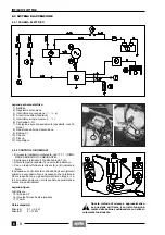
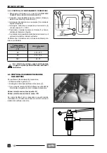
6.6.1 ESQUEMA ELÉCTRICO
Pie de la ilustración del esquema eléctrico
1) Electroventilador
2) Termointerruptor
3) Batería
4) Fusible (20A)
5) Al regulador de tensión
6) Al sistema de alumbrado
7) Interruptor de encendido (
n
-
m
-
s
)
6.6.2 CONTROL DEL FUNCIONAMIENTO
DEL ELECTROVENTILADOR
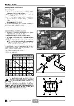
Para controlar el funcionamiento del electroventilador (1):
◆
Desconecte los dos terminales eléctricos (8-9) del ter-
mointerruptor (2) y conéctelos juntos.
Si no funciona:
◆
Controle que el conector (10) esté bien conectado.
◆
Gire manualmente el ventilador y controle que las pa-
letas no toquen el soporte.
Si la rotación no presenta inconvenientes:
◆
Controle el sistema de recarga, véase 6.1 (CONTROL
DEL SISTEMA DE RECARGA) y el fusible de 20A, véa-
se 6.14 (SUBSTITUCIÓN DE LOS FUSIBLES).
6.6.3 CONTROL DEL FUNCIONAMIENTO
DEL TERMOINTERRUPTOR
◆
Extraiga el termointerruptor (2), véase 5.4 (DES-
MONTAJE TERMOINTERRUPTOR LIQUIDO REFRI-
GERANTE).
◆
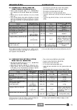
Conecte un tester (11)(ajustado como ohmetro) al ter-
minterruptor (2), como indicado en la figura.
◆
Sumerja el termointerruptor en un recipiente (12) que
contenga líquido refrigerante.
◆
En el mismo recipiente, sumerja un termómetro (13)
con un campo de medida de 0˚ ÷ 150˚C.
◆
Coloque el recipiente arriba de un hornillo (14) y ca-
liente lentamente el líquido.
◆
Controle que la temperatura indicada por el termóme-
tro y el valor del termistor indicado en el tester corres-
pondan a los datos de la tabla.
Si los valores son muy distintos de aquéllos
indicados en la tabla, substituya el termointe-
rruptor.
Temperatura del líquido
refrigerante
(˚C)
Valores estándar
(
Ω
)
inferior a 90˚
∞
superior a 80˚
0
a
6.6 COOLING ELECTROFAN
6.6.1 WIRING DIAGRAM
Wiring diagram key
1) Electrofan
2) Thermal switch
3) Battery
4) Fuse (20A)
5) To voltage regulator
6) To light loads
7) Ignition switch (
n
-
m
-
s
)
6.6.2 CHECKING THE ELECTROFAN OPERATION
To check operation of electrofan (1):
◆
Disconnect the two electrical terminals (8-9) from the
thermal switch (2) and connect them together.
If the electrofan does not function:
◆
Make sure the connector (10) is correctly inserted.
◆
Rotate the fan manually, making sure the blades do
not touch the support.
If the rotation is free from impediments:
◆
Check the recharging system, see 6.1 (CHECKING
THE RECHARGING SYSTEM) and the 20A fuse, see
6.14 (CHANGING THE FUSES).
6.6.3 CHECKING THE THERMAL SWITCH
OPERATION
◆
Remove the thermal switch (2), see 5.4 (REMOVING
THE COOLANT THERMAL SWITCH).
◆
Connect, as illustrated in diagram, a tester (11) (set as
an ohmmeter) to the thermal switch (2).
◆
Dip the thermal switch in a container (12) holding coo-
lant.
◆
Dip in the same container a thermometer (13) with a 0˚
to 150˚C range.
◆
Place the container on a burner (14) and slowly warm
up the liquid.
◆
Check that the temperature reading on the thermome-
ter and the value of the thermal switch indicated on the
tester correspond to the data in the table.
If the values depart excessively from those in-
dicated in the table, change the thermal
switch.
Coolant
temperature
(˚C)
Standard values
(
Ω
)
below 90˚
∞
over 80˚
0
a
Summary of Contents for Pegaso 650
Page 1: ......
Page 3: ...0 4 NOTE NOTES ANMERKUNGEN ...
Page 4: ...1 1 1 2 3 4 5 6 7 8 INFORMAZIONI GENERALI INFORMACIONES GENERALES GENERAL INFORMATION ...
Page 42: ......
Page 69: ...3 1 1 2 3 4 5 6 7 8 MOTORE MOTOR ENGINE ...
Page 90: ...3 22 MOTORE NOTE NOTAS NOTES ...
Page 91: ...4 1 1 2 3 4 5 SISTEMA DI ALIMENTAZIONE SISTEMA DE ALIMENTACIÓN FUEL SYSTEM ...
Page 116: ...4 26 SISTEMA DI ALIMENTAZIONE NOTE NOTAS NOTES ...
Page 117: ...5 1 1 2 3 4 5 6 7 8 IMPIANTO DI RAFFREDDAMENTO SISTEMA DE REFRIGERACIÓN COOLING SYSTEM ...
Page 130: ...5 14 IMPIANTO DI RAFFREDDAMENTO SISTEMA DE REFRIGERACIÓN COOLING SYSTEM NOTE NOTAS NOTES ...
Page 131: ...6 1 6 1 2 3 4 5 6 7 8 IMPIANTO ELETTRICO INSTALACIÓN ELÉCTRICA ELECTRICAL SYSTEM ...
Page 176: ...IMPIANTO ELETTRICO INSTALACIÓN ELÉCTRICA ELECTRICAL SYSTEM 6 46 NOTE NOTAS NOTES ...
Page 177: ...7 1 1 2 3 4 5 6 7 8 CICLISTICA PARTE CICLO CHASSIS PARTS ...
Page 226: ... 67 3 57 2 66 6 3 576 7 50 5827 3267 5 25 58 75 6 5 5 5 ...
Page 242: ... 67 3 57 2 66 6 3 576 7 66 5 12 17 5 25 5 12 17 52 5217 5 ...
Page 246: ... 67 3 57 2 66 6 3 576 7 70 5 12 3267 5 25 5 12 75 6 52 5 5 5 ...
Page 272: ... 67 3 57 2 66 6 3 576 7 96 NOTE NOTAS NOTES ...
Page 311: ...INFORMAZIONI PER LE RIPARAZIONI INFORMACIONES PARA LAS REPARACIONES REPAIRS 8 39 ...


