6
- 23
INSTALACIÓN ELÉCTRICA
ELECTRICAL SYSTEM
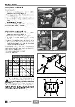
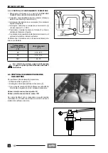
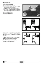
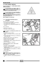
6.7.3 CHECKING THE STARTING RELAY
To check operation of relay :
◆
Remove the fuel tank, see 7.1.1 (REMOVING THE
FUEL TANK).
◆
Disconnect the connector (1).
◆
Slip off the two rubber protections (2-3).
◆
Disconnect the cables (4-5) from the relative terminals
on relay (6).
◆
From relay side, feed with a 12V battery the two inter-
nal terminals of connector (1).
◆
Using a tester (acting as Ohmmeter) check the conti-
nuity between the two screw contacts on the relay.
Correct value with relay fed: 0
Ω
Correct value with relay not fed:
∞
Ω
If the values do not correspond to those indicated, chan-
ge the relay.
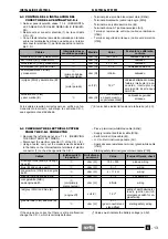
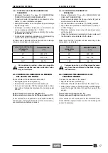
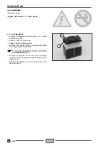
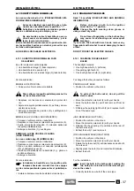
6.7.4 CHECKING THE STAND SWITCH
Perform the following checks:
◆
The stand (1) should rotate freely.
◆
The springs (2) must not be damaged, rusted and/or
weakened.
◆
The switch (3) must be fixed correctly.
To check the operation of the ignition disabling system:
◆
Sit on the saddle.
◆
Lift up the stand and put the gear in neutral.
◆
Start the engine with clutch pulled and engage the ge-
ar.
◆
Lower the stand.
◆
At this point the stand will press the switch, causing
switching off of engine.
If this does not occur, change the switch.
6.7.3 CONTROL DEL RELÉ DE ARRANQUE
Para controlar el funcionamiento del relé:
◆
Desmonte el depositio del combustible, véase 7.1.1
(DESMONTAJE DEPOSITO COMBUSTIBLE).
◆
Desconecte el conector (1).
◆
Extraiga las dos protecciones de goma (2 - 3).
◆
Desconecte los cables (4 - 5) de los terminales corres-
pondientes sobre el relé (6).
◆
Alimente con una batería de 12 V los dos terminales
interiores al conector (1) del lado del relé.
◆
Con un tester (en funcionamiento como ohmetro) con-
trole la continuidad entre los dos contactos de tornillo
sobre el relé.
Valor correcto con relé alimentado: 0
Ω
Valor correcto con relé no alimentado:
∞
Ω
Substituya el relé si los valores que se obtienen no co-
rresponden con aquéllos indicados.
6.7.4 CONTROL DEL INTERRUPTOR DEL CABALLETE
Efectúe los siguientes controles:
◆
El caballete (1) debe girar libremente.
◆
Los muelles (2) no deben estar dañados, oxidados
ni/o debilitados.
◆
El interruptor (3) debe estar fijado correctamente.
Para controlar el funcionamiento del sistema de bloqueo
del encendido:
◆
Suba al sillín.
◆
Levante el caballete y ponga el cambio en punto muer-
to.
◆
Arranque el motor con el embrague puesto y ponga la
marcha.
◆
Baje el caballete.
◆
En este momento, el caballete debe empujar el inte-
rruptor que apagará el motor.
Si ésto no sucediese, substituya el interruptor.
Summary of Contents for Pegaso 650
Page 1: ......
Page 3: ...0 4 NOTE NOTES ANMERKUNGEN ...
Page 4: ...1 1 1 2 3 4 5 6 7 8 INFORMAZIONI GENERALI INFORMACIONES GENERALES GENERAL INFORMATION ...
Page 42: ......
Page 69: ...3 1 1 2 3 4 5 6 7 8 MOTORE MOTOR ENGINE ...
Page 90: ...3 22 MOTORE NOTE NOTAS NOTES ...
Page 91: ...4 1 1 2 3 4 5 SISTEMA DI ALIMENTAZIONE SISTEMA DE ALIMENTACIÓN FUEL SYSTEM ...
Page 116: ...4 26 SISTEMA DI ALIMENTAZIONE NOTE NOTAS NOTES ...
Page 117: ...5 1 1 2 3 4 5 6 7 8 IMPIANTO DI RAFFREDDAMENTO SISTEMA DE REFRIGERACIÓN COOLING SYSTEM ...
Page 130: ...5 14 IMPIANTO DI RAFFREDDAMENTO SISTEMA DE REFRIGERACIÓN COOLING SYSTEM NOTE NOTAS NOTES ...
Page 131: ...6 1 6 1 2 3 4 5 6 7 8 IMPIANTO ELETTRICO INSTALACIÓN ELÉCTRICA ELECTRICAL SYSTEM ...
Page 176: ...IMPIANTO ELETTRICO INSTALACIÓN ELÉCTRICA ELECTRICAL SYSTEM 6 46 NOTE NOTAS NOTES ...
Page 177: ...7 1 1 2 3 4 5 6 7 8 CICLISTICA PARTE CICLO CHASSIS PARTS ...
Page 226: ... 67 3 57 2 66 6 3 576 7 50 5827 3267 5 25 58 75 6 5 5 5 ...
Page 242: ... 67 3 57 2 66 6 3 576 7 66 5 12 17 5 25 5 12 17 52 5217 5 ...
Page 246: ... 67 3 57 2 66 6 3 576 7 70 5 12 3267 5 25 5 12 75 6 52 5 5 5 ...
Page 272: ... 67 3 57 2 66 6 3 576 7 96 NOTE NOTAS NOTES ...
Page 311: ...INFORMAZIONI PER LE RIPARAZIONI INFORMACIONES PARA LAS REPARACIONES REPAIRS 8 39 ...


