7
- 17
3$57(&,&/2
&+$66,63$576
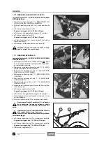
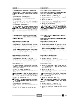
7.1.12 DESMONTAJE CAJA FILTRO
Lea con cuidado 1.4 (PRECAUCIONES E INFORMA-
CIONES GENERALES) y 2.3 (BATERÍA).
X
Coloque el vehículo sobre el caballete central
-
o
sobre un especial caballete de sostén fijado en los pi-
votes del caballete central.
X
Quite la batería, véase 7.1.13 (DESMONTAJE BATE-
RIA).
X
Quite los silenciadores de escape, véase 7.1.10 (DES-
MONTAJE SILENCIADORES DE ESCAPE).
Prepare la abrazadera ajustable para sustituir-
la a la original (de tipo especial sin tornillo).
X
Corte la cabeza de la abrazadera (1).
X
Extraiga el tubo de purga aceite (2).
X
Desplace la abrazadera (3).
X
Extraiga el tubo (4) de drenaje de las impurezas.
X
Desplace la abrazadera (5).
X
Extraiga el tubo de escape (6).
X
Destornille y quite el tornillo (7) soltando la abrazadera
(8).
Durante el reensamblaje coloque correcta-
mente el tubo de escape (6) y la abrazadera
(8).
X
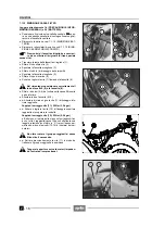
Extraiga los dos tubos (4-6) del collar de la parte infe-
rior de la caja de filtro.
X
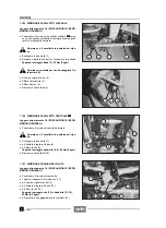
Afloje las dos abrazaderas (9-10).
X
+
Destornille de aproximadamente un giro el tornillo
(11) de sujeción inferior del vástago del sillín.
Par de apriete tornillo (11): 25 Nm (2,5 kgm)
X
+
Destornille y quite el tornillo (12) de sujeción supe-
rior del vástago del sillín y guarde la arandela.
Par de apriete tornillo (12): 25 Nm (2,5 kgm)
X
Golpee con la palma de la mano sobre el portaequipa-
jes hasta que el grupo vástago del sillín/caja del filtro
realice una ligera rotación (con fulcro en “A”) hacia
abajo, de tal forma los dos manguitos (13-14) se suel-
tan de los carburadores.
No gire el grupo vástago del sillín/caja del fil-
tro más de lo necesario.
X
+
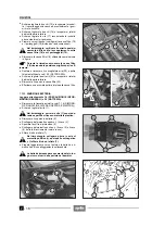
Apriete provisionalmente el tornillo (11) para mante-
ner el grupo vástago del sillín en posición.
Tape las aberturas de los tubos de escape im-
pidiendo la entrada de cuerpos exteriores.
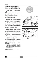
7.1.12 REMOVING THE AIR CLEANER CASING
Read 1.4 (PRECAUTIONS AND GENERAL INFORMA-
TION) and 2.3 (BATTERY) carefully.
X
Position the vehicle on the centre stand
-
or on an
apposite support stand fixed to the centre stand cou-
plings.
X
Remove the battery, see 7.1.13 (REMOVING THE
BATTERY).
X
Remove the exhaust silencers, see 7.1.10 (REMOV-
ING THE EXHAUST SILENCERS).
Get a screwdriver-type pipe clamp, to replace
the original one (special type without screw).
X
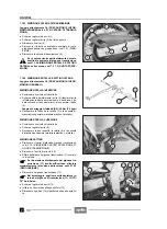
Cut the head of the pipe clamp (1).
X
Withdraw the oil breather pipe (2).
X
Shift the pipe clamp (3).
X
Withdraw the impurities drain pipe (4).
X
Shift the pipe clamp (5).
X
Withdraw the exhaust pipe (6).
X
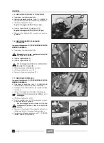
Unscrew and remove the screw (7), releasing the
clamp (8).
Upon reassembly, position the exhaust pipe
(6) and the clamp (8) correctly.
X
Withdraw the two pipes (4-6) from the collar on the
lower part of the air cleaner casing.
X
Loosen the two clamps (9-10).
X
+
Loosen (about one turn) the screw (11) that fastens
the lower part of the saddle pillar.
Screw (11) driving torque: 25 Nm (2.5 kgm).
X
+
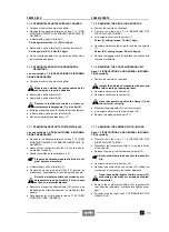
Unscrew and remove the screw (12) that fastens the
upper part of the saddle pillar and take the washer.
Screw (12) driving torque: 25 Nm (2.5 kgm).
X
Strike the luggage rack with the palm of your hand until
the whole saddle pillar/filter casing unit performs a
slight downward rotation (with fulcrum in “A), thus al-
lowing the two couplings (13-14) to be released from
the carburettors.
Do not make the saddle pillar/filter casing unit
rotate more than necessary.
X
+
Tighten the screw (11) temporarily, in such a way as
to keep the saddle pillar unit in the right position.
Plug the carburettor openings, to avoid any
accidental introduction of foreign matters.
Summary of Contents for Pegaso 650
Page 1: ......
Page 3: ...0 4 NOTE NOTES ANMERKUNGEN ...
Page 4: ...1 1 1 2 3 4 5 6 7 8 INFORMAZIONI GENERALI INFORMACIONES GENERALES GENERAL INFORMATION ...
Page 42: ......
Page 69: ...3 1 1 2 3 4 5 6 7 8 MOTORE MOTOR ENGINE ...
Page 90: ...3 22 MOTORE NOTE NOTAS NOTES ...
Page 91: ...4 1 1 2 3 4 5 SISTEMA DI ALIMENTAZIONE SISTEMA DE ALIMENTACIÓN FUEL SYSTEM ...
Page 116: ...4 26 SISTEMA DI ALIMENTAZIONE NOTE NOTAS NOTES ...
Page 117: ...5 1 1 2 3 4 5 6 7 8 IMPIANTO DI RAFFREDDAMENTO SISTEMA DE REFRIGERACIÓN COOLING SYSTEM ...
Page 130: ...5 14 IMPIANTO DI RAFFREDDAMENTO SISTEMA DE REFRIGERACIÓN COOLING SYSTEM NOTE NOTAS NOTES ...
Page 131: ...6 1 6 1 2 3 4 5 6 7 8 IMPIANTO ELETTRICO INSTALACIÓN ELÉCTRICA ELECTRICAL SYSTEM ...
Page 176: ...IMPIANTO ELETTRICO INSTALACIÓN ELÉCTRICA ELECTRICAL SYSTEM 6 46 NOTE NOTAS NOTES ...
Page 177: ...7 1 1 2 3 4 5 6 7 8 CICLISTICA PARTE CICLO CHASSIS PARTS ...
Page 226: ... 67 3 57 2 66 6 3 576 7 50 5827 3267 5 25 58 75 6 5 5 5 ...
Page 242: ... 67 3 57 2 66 6 3 576 7 66 5 12 17 5 25 5 12 17 52 5217 5 ...
Page 246: ... 67 3 57 2 66 6 3 576 7 70 5 12 3267 5 25 5 12 75 6 52 5 5 5 ...
Page 272: ... 67 3 57 2 66 6 3 576 7 96 NOTE NOTAS NOTES ...
Page 311: ...INFORMAZIONI PER LE RIPARAZIONI INFORMACIONES PARA LAS REPARACIONES REPAIRS 8 39 ...

