2
- 47
OPERACIONES DE MANTENIMIENTO PERIÓDICO Y DE
PUESTA A PUNTO
PERIODIC SERVICE AND SETTING UP OPERATIONS
2.25 HORQUILLA DELANTERA
Lea con mucha atención 1.4 (PRECAUCIONES E IN-
FORMACIONES GENERALES).
Substituya el aceite horquilla delantera cada 12000 km (o
16 meses).
En caso de que note que la horquilla se hunde excesiva-
mente, es necesario controlar el nivel de aceite en las ba-
rras, véase 7.8.1 (CONTROL NIVEL ACEITE).
Controle que la horquilla no tenga pérdidas de aceite y
que la superficie exterior de las barras no estén rayadas
o tengan ranuras.
En dicho caso, substituya todas las piezas dañadas.
2.26 HORQUILLA TRASERA
Lea con mucha atención 1.4 (PRECAUCIONES E IN-
FORMACIONES GENERALES).
Controle periódicamente el juego de apriete del eje y de
los cojinetes de agujas de la horquilla trasera.
Para el control:
◆
Saque el protector de carter, véase 7.1.9 (DESMON-
TAJE PROTECTOR DE CARTER).
A causa del peso y del espacio que ocupa el
vehículo, la operación que sigue a continua-
ción necesita la intervención de un segundo
operador. Siga adelante con cuidado y compruebe si
puede soportar el peso del vehículo.
Peso en vacío del vehículo (en orden de mar-
cha): 200 kg.
◆
Levante la parte trasera del vehículo y coloque un so-
porte adecuado (con altura 350 mm) por debajo del
motor de manera que la rueda trasera tenga espacio
suficiente para moverse libremente y para evitar la
caída del vehículo.
◆
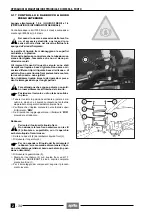
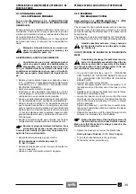
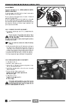
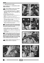
Sacuda la reda verticalmente y trasversalmente en el
sentido de marcha (véase figuras).
En caso de que note un juego, ajuste el basculante,
véase 2.26.1 (AJUSTE BASCULANTE).
Si el juego continúa, sustituya los cojinetes, véase
7.10 (SUSPENSION TRASERA).
2.26.1 AJUSTE BASCULANTE
Lea con cuidado 1.4 (PRECAUCIONES E INFORMA-
CIONES GENERALES).
◆
Coloque el vehículo sobre el caballete central
&
o
sobre un adecuado caballete de soporte fijado en los
pivotes del caballete central.
◆
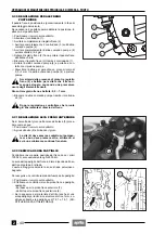
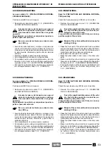
Bloquee la tuerca de regulación (1), desenrosque la
tuerca de bloqueo (2) utilizando la llave tubular corres-
pondiente, véase 1.8 (EQUIPOS ESPECIALES).
◆
Enrosque la tuerca de regulación (1) hasta que llegue
al tope sobre el basculante, luego enrósquela de 1/4
de vuelta.
Par de apriete tuerca de regulación (1) : co
1/4 de vuelta.
◆
Bloquee la tuerca de regulación (1), apriete el eje bas-
culante (3).
Par de apriete eje (3) : 100 Nm (10 kgm).
◆
Mantenga bloqueada la tuerca de regulación (1) y, a la
vez, enrosque la tuerca de bloqueo (2).
Par de apriete tuerca de bloqueo (2):
100 Nm (10 kgm).
a
c
2.25 FRONT FORK
Read 1.4 carefully (PRECAUTIONS AND GENERAL
INFORMATION).
Replace the front fork oil every 12000 km (or 16 months).
Should the fork reach the end of its stroke, check the oil
level of the fork tubes, see 7.8.1 (CHECKING THE OIL
LEVEL).
Make sure there are no oil leaks and that the outer sur-
face of the tubes is neither scratched nor grooved.
If so, replace all the damaged parts.
2.26 REAR FORK
Read 1.4 carefully (PRECAUTIONS AND GENERAL
INFORMATION).
Periodically check the tightening of the pin and of the
needle bearings of the rear fork.
To carry out this operation, proceed as follows:
◆
Remove the oil pan guard, see 7.1.9 (REMOVING
THE OIL PAN GUARD).
Due to the weight and dimensions of the vehi-
cle, the following operation cannot be per-
formed by one person only.
Proceed with care and make sure that you can sup-
port the weight of the vehicle.
Weight of the vehicle without driver (ready for
starting): 200 kg.
◆
Raise the rear part of the vehicle, have a suitable sup-
port (the height of which should be 350 mm) placed
under the engine, so that the rear wheel can rotate
freely and the vehicle cannot fall down.
◆
Shake the wheel vertically and trasversally to the di-
rection of travel (see figure).
If you find any slack, adjust the rear fork, see 2.26.1
(ADJUSTING THE REAR FORK).
If the slack persists, adjust the bearings, see 7.10
(REAR SUSPENSION).
2.26.1 ADJUSTING THE REAR FORK
Read 1.4 (PRECAUTIONS AND GENERAL INFORMA-
TION) carefully.
◆
Position the vehicle on the centre stand
&
or on an
apposite support fixed to the centre stand couplings.
◆
Lock the adjusting bush (1), unscrew the locking ring
(2) by means of the apposite socket spanner, see 1.8
(SPECIAL TOOLS).
◆
Screw the adjusting bush (1) until it strikes against the
rear fork, then give it another one fourth turn.
Adjusting bush (1) driving torque:
c one fourth turn.
◆
Lock the adjusting bush (1), tighten the rear fork pin
(3).
Pin (3) driving torque: 100 Nm (10 kgm).
◆
Hold the adjusting bush (1) and at the same time
screw the locking ring (2).
Locking ring (2) driving torque: 100 Nm (10 kgm).
a
c
Summary of Contents for Pegaso 650
Page 1: ......
Page 3: ...0 4 NOTE NOTES ANMERKUNGEN ...
Page 4: ...1 1 1 2 3 4 5 6 7 8 INFORMAZIONI GENERALI INFORMACIONES GENERALES GENERAL INFORMATION ...
Page 42: ......
Page 69: ...3 1 1 2 3 4 5 6 7 8 MOTORE MOTOR ENGINE ...
Page 90: ...3 22 MOTORE NOTE NOTAS NOTES ...
Page 91: ...4 1 1 2 3 4 5 SISTEMA DI ALIMENTAZIONE SISTEMA DE ALIMENTACIÓN FUEL SYSTEM ...
Page 116: ...4 26 SISTEMA DI ALIMENTAZIONE NOTE NOTAS NOTES ...
Page 117: ...5 1 1 2 3 4 5 6 7 8 IMPIANTO DI RAFFREDDAMENTO SISTEMA DE REFRIGERACIÓN COOLING SYSTEM ...
Page 130: ...5 14 IMPIANTO DI RAFFREDDAMENTO SISTEMA DE REFRIGERACIÓN COOLING SYSTEM NOTE NOTAS NOTES ...
Page 131: ...6 1 6 1 2 3 4 5 6 7 8 IMPIANTO ELETTRICO INSTALACIÓN ELÉCTRICA ELECTRICAL SYSTEM ...
Page 176: ...IMPIANTO ELETTRICO INSTALACIÓN ELÉCTRICA ELECTRICAL SYSTEM 6 46 NOTE NOTAS NOTES ...
Page 177: ...7 1 1 2 3 4 5 6 7 8 CICLISTICA PARTE CICLO CHASSIS PARTS ...
Page 226: ... 67 3 57 2 66 6 3 576 7 50 5827 3267 5 25 58 75 6 5 5 5 ...
Page 242: ... 67 3 57 2 66 6 3 576 7 66 5 12 17 5 25 5 12 17 52 5217 5 ...
Page 246: ... 67 3 57 2 66 6 3 576 7 70 5 12 3267 5 25 5 12 75 6 52 5 5 5 ...
Page 272: ... 67 3 57 2 66 6 3 576 7 96 NOTE NOTAS NOTES ...
Page 311: ...INFORMAZIONI PER LE RIPARAZIONI INFORMACIONES PARA LAS REPARACIONES REPAIRS 8 39 ...


