7
- 31
3$57(&,&/2
&+$66,63$576
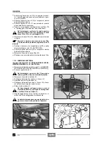
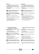
7.1.23 DESMONTAJE CADENA DE TRANSMISION
Lea con cuidado 1.4 (PRECAUCIONES E INFORMA-
CIONES GENERALES) y 2.16 (CADENA DE TRANSMI-
SIÓN).
X
Destornille y quite los dos tornillos (1).
X
Destornille y quite el tornillo (2) del lado opuesto.
X
Quite el cárter (3).
X
Quite el basculante junto con la rueda, el grupo de
suspensión y el grupo freno, véase 7.9.1 (DESMON-
TAJE).
X
Quite la cadena de transmisión (4).
Si la cadena está muy desgastada, sustitúyala
junto con el piñón de transmisión, véase
7.1.24 (DESMONTAJE RODILLOS Y PATIN CA-
DENA) y con la corona, véase 7.3 (RUEDA TRASE-
RA).
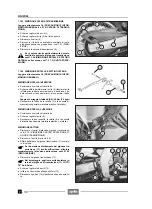
7.1.24 DESMONTAJE RODILLOS Y PATIN CADENA
Lea con cuidado 1.4 (PRECAUCIONES E INFORMA-
CIONES GENERALES).
DESMONTAJE RODILLO INFERIOR
X
Coloque el vehículo sobre el caballete.
X
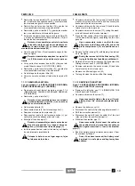
Destornille y quite parcialmente el tornillo (5) (deje el
tornillo insertado lo suficiente para mantener en posi-
ción el pedal de mando freno trasero) y guarde la tuer-
ca (6).
Par de apriete tornillo/tuerca (5-6): 25 Nm (2,5 kgm)
X
Guarde la arandela, el rodillo (7) y el casquillo distan-
ciador especial (material plástico + metal).
DESMONTAJE RODILLO SUPERIOR
X
Coloque el vehículo sobre el caballete.
X
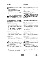
Destornille y quite parcialmente el tornillo (8).
X
Guarde las dos arandelas, el rodillo (9) y el casquillo
distanciador especial (material plástico + metal).
DESMONTAJE PATIN
X
Quite el cárter de protección piñón de transmisión,
véase 3.1.3 (DESMONTAJE CARTER PROTECCION
PIÑON TRANSMISION).
X
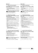
Quite el anillo anillo de seguridad (10).
X
Extraiga del eje el piñón de transmisión (11) junto con
la cadena.
Si la operación de extracción del piñón de
transmisión (11) resulta algo difícil, afloje un
poco la tensión de la cadena, véase 2.16.3 (AJUSTE).
X
Quite el piñón de transmisión (11).
Durante la instalación aplique sobre el denta-
do interior del piñón de transmisión (11) LOC-
TITE
®
Anti-Seize.
X
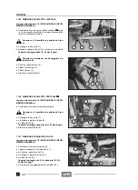
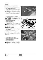
Destornille y quite los dos tornillos (12).
X
Inserte un destornillador en el correspondiente hueco
(13).
X
Quite el patín (14) extrayéndolo del lado delantero.
7.1.23 REMOVING THE GEARING CHAIN
Read 1.4 (PRECAUTIONS AND GENERAL INFORMA-
TION) and 2.16 (DRIVING CHAIN) carefully.
X
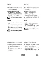
Unscrew and remove the two screws (1).
X
Unscrew and remove the screw (2) from the opposite
side.
X
Remove the casing (3).
X
Remove the rear fork complete with wheel, suspension
unit and brake unit, see 7.9.1 (REMOVAL).
X
Remove the gearing chain (4).
If the chain is excessively worn, change it to-
gether with the transmission pinion, see
7.1.24 (REMOVING THE CHAIN ROLLERS AND
THE CHAIN SHOE), and with the crown gear, see 7.3
(REAR WHEEL).
7.1.24 REMOVING THE CHAIN ROLLERS AND THE
CHAIN SHOE
Read 1.4 (PRECAUTIONS AND GENERAL INFORMA-
TION) carefully.
REMOVING THE LOWER ROLLER
X
Position the vehicle on the stand.
X
Unscrew and partially withdraw the screw (5) (let the
screw in as much as necessary to keep the rear brake
pedal in the right position) and take the nut (6).
Screw/nut (5-6) driving torque: 25 Nm (2.5 kgm).
X
Take the washer, the roller (7) and the special spacing
bush (p metal).
REMOVING THE UPPER ROLLER
X
Position the vehicle on the stand.
X
Unscrew and remove the screw (8).
X
Take the two washers, the roller (9) and the special
spacing bush (p metal).
REMOVING THE SHOE
X
Remove the transmission pinion protection case, see
3.1.3 (REMOVING THE TRANSMISSION PINION
PROTECTION CASE).
X
Remove the stop ring (10).
X
Withdraw the transmission pinion (11) complete with
chain from the shaft.
It it is difficult to withdraw the transmission
pinion (11), slightly slacken the chain, see
2.16.3 (ADJUSTMENT).
X
Remove the transmission pinion (11).
Upon reassembly, apply LOCTITE
®
Anti-Seize
on the inner toothing of the transmission pi-
nion (11).
X
Unscrew and remove the two screws (12).
X
Insert a screwdriver in the apposite hole (13).
X
Remove the shoe (14) by withdrawing it from the front
part.
Summary of Contents for Pegaso 650
Page 1: ......
Page 3: ...0 4 NOTE NOTES ANMERKUNGEN ...
Page 4: ...1 1 1 2 3 4 5 6 7 8 INFORMAZIONI GENERALI INFORMACIONES GENERALES GENERAL INFORMATION ...
Page 42: ......
Page 69: ...3 1 1 2 3 4 5 6 7 8 MOTORE MOTOR ENGINE ...
Page 90: ...3 22 MOTORE NOTE NOTAS NOTES ...
Page 91: ...4 1 1 2 3 4 5 SISTEMA DI ALIMENTAZIONE SISTEMA DE ALIMENTACIÓN FUEL SYSTEM ...
Page 116: ...4 26 SISTEMA DI ALIMENTAZIONE NOTE NOTAS NOTES ...
Page 117: ...5 1 1 2 3 4 5 6 7 8 IMPIANTO DI RAFFREDDAMENTO SISTEMA DE REFRIGERACIÓN COOLING SYSTEM ...
Page 130: ...5 14 IMPIANTO DI RAFFREDDAMENTO SISTEMA DE REFRIGERACIÓN COOLING SYSTEM NOTE NOTAS NOTES ...
Page 131: ...6 1 6 1 2 3 4 5 6 7 8 IMPIANTO ELETTRICO INSTALACIÓN ELÉCTRICA ELECTRICAL SYSTEM ...
Page 176: ...IMPIANTO ELETTRICO INSTALACIÓN ELÉCTRICA ELECTRICAL SYSTEM 6 46 NOTE NOTAS NOTES ...
Page 177: ...7 1 1 2 3 4 5 6 7 8 CICLISTICA PARTE CICLO CHASSIS PARTS ...
Page 226: ... 67 3 57 2 66 6 3 576 7 50 5827 3267 5 25 58 75 6 5 5 5 ...
Page 242: ... 67 3 57 2 66 6 3 576 7 66 5 12 17 5 25 5 12 17 52 5217 5 ...
Page 246: ... 67 3 57 2 66 6 3 576 7 70 5 12 3267 5 25 5 12 75 6 52 5 5 5 ...
Page 272: ... 67 3 57 2 66 6 3 576 7 96 NOTE NOTAS NOTES ...
Page 311: ...INFORMAZIONI PER LE RIPARAZIONI INFORMACIONES PARA LAS REPARACIONES REPAIRS 8 39 ...


