7
- 33
3$57(&,&/2
&+$66,63$576
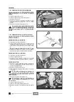
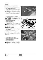
7.1.25 DESMONTAJE CABALLETE LATERAL
Lea con cuidado 1.4 (PRECAUCIONES E INFORMA-
CIONES GENERALES).
X
Coloque el vehículo sobre el caballete central
-
o
bien sobre un especial caballete de sostén fijado a los
ataques del caballete central.
Actúe con el caballete en posición de reposo.
X
Desconecte los dos resortes (1).
X
Afloje y quite la tuerca (2) y guarde la arandela.
Par de apriete tuerca (2): 30 Nm (3 kgm)
Actúe con mucho cuidado para no dañar el in-
terruptor (3).
X
Destornille y quite el tornillo (4).
X
Extraiga el interruptor (3).
X
Extraiga el perno (5).
X
Quite el caballete (6).
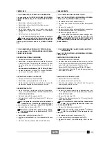
7.1.26 DESMONTAJE CABALLETE CENTRAL
-
Lea con cuidado 1.4 (PRECAUCIONES E INFORMA-
CIONES GENERALES).
X
Coloque el vehículo sobre el caballete lateral.
Actúe con el caballete en posición de reposo.
X
Desconecte los dos resortes (7).
X
+
Afloje y quite la tuerca (8).
X
+
Quite el tornillo (9).
Par de apriete tuerca/tornillo (8-9): 80 Nm (8 kgm)
X
Quite el caballete (10).
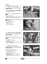
7.1.27 DESMONTAJE ESTRIBO PILOTO
Lea con cuidado 1.4 (PRECAUCIONES E INFORMA-
CIONES GENERALES).
X
Coloque el vehículo sobre el caballete.
X
Quite el casquillo protector (11).
X
+
Destornille y quite el tornillo (12).
X
Afloje y quite la tuerca (13).
X
Quite el tornillo (14).
Par de apriete tornillo (12) y tuerca/tornillo (13-14):
50 Nm (5 kgm)
X
Quite el estribo piloto completo (15).
7.1.25 REMOVING THE SIDE STAND
Read 1.4 (PRECAUTIONS AND GENERAL INFORMA-
TION) carefully.
X
Position the vehicle on the centre stand
-
or on an
apposite support stand fixed to the centre stand cou-
plings.
Proceed with the stand up.
X
Disconnect the two springs (1).
X
Loosen and remove the nut (2) and take the washer.
Nut (2) driving torque: 30 Nm (3 kgm).
Proceed with care, in order to avoid damaging
the switch (3).
X
Unscrew and remove the screw (4).
X
Withdraw the switch (3).
X
Withdraw the pin (5).
X
Remove the stand (6).
7.1.26 REMOVING THE CENTRE STAND
-
Read 1.4 (PRECAUTIONS AND GENERAL INFORMA-
TION) carefully.
X
Position the vehicle on the side stand.
Proceed with the stand up.
X
Disconnect the two springs (7).
X
+
Loosen and remove the nut (8).
X
+
Withdraw the screw (9).
Nut/screw (8-9) driving torque: 80 Nm (8 kgm)
X
Remove the stand (10).
7.1.27 REMOVING THE RIDER’S FOOTBOARD
Read 1.4 (PRECAUTIONS AND GENERAL INFORMA-
TION) carefully.
X
Position the vehicle on the stand.
X
Remove the protection cap (11).
X
+
Unscrew and remove the screw (12).
X
Loosen and remove the nut (13).
X
Withdraw the screw (14).
Screw (12) and nut/screw (13-14) driving torque:
50 Nm (5 kgm).
X
Remove the rider's footboard (15).
Summary of Contents for Pegaso 650
Page 1: ......
Page 3: ...0 4 NOTE NOTES ANMERKUNGEN ...
Page 4: ...1 1 1 2 3 4 5 6 7 8 INFORMAZIONI GENERALI INFORMACIONES GENERALES GENERAL INFORMATION ...
Page 42: ......
Page 69: ...3 1 1 2 3 4 5 6 7 8 MOTORE MOTOR ENGINE ...
Page 90: ...3 22 MOTORE NOTE NOTAS NOTES ...
Page 91: ...4 1 1 2 3 4 5 SISTEMA DI ALIMENTAZIONE SISTEMA DE ALIMENTACIÓN FUEL SYSTEM ...
Page 116: ...4 26 SISTEMA DI ALIMENTAZIONE NOTE NOTAS NOTES ...
Page 117: ...5 1 1 2 3 4 5 6 7 8 IMPIANTO DI RAFFREDDAMENTO SISTEMA DE REFRIGERACIÓN COOLING SYSTEM ...
Page 130: ...5 14 IMPIANTO DI RAFFREDDAMENTO SISTEMA DE REFRIGERACIÓN COOLING SYSTEM NOTE NOTAS NOTES ...
Page 131: ...6 1 6 1 2 3 4 5 6 7 8 IMPIANTO ELETTRICO INSTALACIÓN ELÉCTRICA ELECTRICAL SYSTEM ...
Page 176: ...IMPIANTO ELETTRICO INSTALACIÓN ELÉCTRICA ELECTRICAL SYSTEM 6 46 NOTE NOTAS NOTES ...
Page 177: ...7 1 1 2 3 4 5 6 7 8 CICLISTICA PARTE CICLO CHASSIS PARTS ...
Page 226: ... 67 3 57 2 66 6 3 576 7 50 5827 3267 5 25 58 75 6 5 5 5 ...
Page 242: ... 67 3 57 2 66 6 3 576 7 66 5 12 17 5 25 5 12 17 52 5217 5 ...
Page 246: ... 67 3 57 2 66 6 3 576 7 70 5 12 3267 5 25 5 12 75 6 52 5 5 5 ...
Page 272: ... 67 3 57 2 66 6 3 576 7 96 NOTE NOTAS NOTES ...
Page 311: ...INFORMAZIONI PER LE RIPARAZIONI INFORMACIONES PARA LAS REPARACIONES REPAIRS 8 39 ...

