7
- 35
3$57(&,&/2
&+$66,63$576
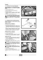
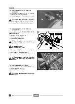
7.1.28 DESMONTAJE MANILLAR
X
Desmonte los mandos y los puños, véase 7.1.21
(DESMONTAJE MANDOS / PUÑOS).
X
+
Suelte los cables de las dos abrazaderas (1).
Prepare el mismo número de abrazaderas
para sustituirlas a las originales durante el
reensamblaje.
X
+
Destornille y quite los dos tornillos (2).
X
+
Quite el semicasco (3) junto con el retrovisor.
X
Desplace el semicasco (4) junto con la palanca de
mando embrague (en el lado derecho bomba/palanca
de mando freno delantero).
X
+
Quite el elemento de goma de protección (5).
X
+
Destornille y quite los dos tornillos (6).
Par de apriete tornillos (6): 25 Nm (2,5 kgm)
X
+
Quite el perno de U (7).
X
Quite el manillar (8).
Durante el reensamblaje coloque a la altura
correcta la palanca de mando freno delantero
y la palanca de mando embrague.
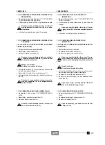
7.1.29 DESMONTAJE RETROVISORES
X
+
Levante el elemento de protección (9).
X
+
Destornille totalmente el tornillo (10) y quite el retro-
visor (11) completo.
Después del reensamblaje ajuste, si es necesario, el re-
trovisor:
X
+
Afloje unos giros la tuerca (12).
X
+
Gire el retrovisor (11) en la posición más adecuada.
X
+
Apriete la tuerca (12).
X
+
Vuelva a Colocar el elemento de protección (9).
7.1.28 REMOVING THE HANDLEBARS
X
Remove the controls and handgrips, see 7.1.21 (RE-
MOVING THE CONTROLS/HANDGRIPS).
X
+
Release the cables from the two fastening clamps
(1).
Get other clamps to be used for the reassem-
bly.
X
+
Unscrew and remove the two screws (2).
X
+
Remove the half-shell (3) complete with the rear-
view mirror.
X
Shift the half-shell (4) complete with the clutch control
lever (on the right side of the front brake lever/pump).
X
+
Remove the rubber protection element (5).
X
+
Unscrew and remove the two screws (6).
Screw (6) driving torque: 25 Nm (2.5 kgm).
X
+
Remove the U-bolt (7).
X
Remove the handlebars (8).
Upon reassembly, position the front brake le-
ver and the clutch control lever at the right
height.
7.1.29 REMOVING THE REAR-VIEW MIRRORS
X
+
Lift the protection element (9).
X
+
Unscrew the screw (10) completely and remove the
whole rear-view mirror (11).
After the reassembly, if necessary adjust the mirror:
X
+
Loosen the nut (12).
X
+
Turn the mirror (11) to its optimal position.
X
+
Tighten the nut (12).
X
+
Put back the protection element (9).
Summary of Contents for Pegaso 650
Page 1: ......
Page 3: ...0 4 NOTE NOTES ANMERKUNGEN ...
Page 4: ...1 1 1 2 3 4 5 6 7 8 INFORMAZIONI GENERALI INFORMACIONES GENERALES GENERAL INFORMATION ...
Page 42: ......
Page 69: ...3 1 1 2 3 4 5 6 7 8 MOTORE MOTOR ENGINE ...
Page 90: ...3 22 MOTORE NOTE NOTAS NOTES ...
Page 91: ...4 1 1 2 3 4 5 SISTEMA DI ALIMENTAZIONE SISTEMA DE ALIMENTACIÓN FUEL SYSTEM ...
Page 116: ...4 26 SISTEMA DI ALIMENTAZIONE NOTE NOTAS NOTES ...
Page 117: ...5 1 1 2 3 4 5 6 7 8 IMPIANTO DI RAFFREDDAMENTO SISTEMA DE REFRIGERACIÓN COOLING SYSTEM ...
Page 130: ...5 14 IMPIANTO DI RAFFREDDAMENTO SISTEMA DE REFRIGERACIÓN COOLING SYSTEM NOTE NOTAS NOTES ...
Page 131: ...6 1 6 1 2 3 4 5 6 7 8 IMPIANTO ELETTRICO INSTALACIÓN ELÉCTRICA ELECTRICAL SYSTEM ...
Page 176: ...IMPIANTO ELETTRICO INSTALACIÓN ELÉCTRICA ELECTRICAL SYSTEM 6 46 NOTE NOTAS NOTES ...
Page 177: ...7 1 1 2 3 4 5 6 7 8 CICLISTICA PARTE CICLO CHASSIS PARTS ...
Page 226: ... 67 3 57 2 66 6 3 576 7 50 5827 3267 5 25 58 75 6 5 5 5 ...
Page 242: ... 67 3 57 2 66 6 3 576 7 66 5 12 17 5 25 5 12 17 52 5217 5 ...
Page 246: ... 67 3 57 2 66 6 3 576 7 70 5 12 3267 5 25 5 12 75 6 52 5 5 5 ...
Page 272: ... 67 3 57 2 66 6 3 576 7 96 NOTE NOTAS NOTES ...
Page 311: ...INFORMAZIONI PER LE RIPARAZIONI INFORMACIONES PARA LAS REPARACIONES REPAIRS 8 39 ...


