7
- 57
3$57(&,&/2
&+$66,63$576
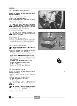
7.3.4 REINSTALACION
Lea con mucho cuidado 1.4 (PRECAUCIONES E IN-
FORMACIONES GENERALES).
Ponga cuidado al introducir el disco en la pin-
za del freno.
X
Coloque la rueda trasera entre las barras del bascu-
lante.
X
Haga avanzar la rueda y coloque la cadena de trans-
misión (1) sobre la corona dentada (2).
Peligro de lesiones.
No introduzca los dedos para alinear los aloja-
mientos.
X
Ponga hacia atrás la rueda alineando el alojamiento
del eje sobre el cubo de la rueda con los alojamientos
del eje sobre los brazos del basculante.
Engrase el eje de la rueda, véase 1.7 (TABLA
DE LOS LUBRICANTES).
Para favorecer la introducción del eje de la
rueda, levante moderadamente la rueda.
X
Introduzca, desde el lado izquierdo del vehículo, el eje
de la rueda (3) junto con su correspondiente arandela
(4).
Controle si se ha introducido del todo el eje de
la rueda.
X
Introduzca la arandela (5) y enrosque del todo la tuer-
ca (6).
X
Controle la tensión de la cadena, véase 2.16.1 (CON-
TROL DEL JUEGO).
X
Bloquee, con la llave correspondiente, la rotación del
eje de la rueda (3) y apriete la tuerca (6).
Par de apriete tuerca-eje rueda (6-3):
100 Nm (10 kgm).
A causa del peso y del espacio que ocupa el
vehículo, la operación que sigue a continua-
ción necesita la intervención de un segundo
operador.
Siga adelante con cuidado y compruebe si puede so-
portar el peso del vehículo.
Peso en vacío del vehículo (en orden de mar-
cha): 200 kg.
X
Levante la parte trasera del vehículo y desplace el so-
porte que se había colocado por debajo del motor du-
rante el desmontaje.
X
Baje el vehículo y colóquelo sobre el caballete.
X
Monte correctamente el protector de cárter, véase
7.1.9 (DESMONTAJE PROTECTOR DE CARTER).
Tras haber concluido la instalación, accione
varias veces la palanca del freno trasero y
controle el funcionamiento correcto del siste-
ma de frenado.
Controle el centrado y el equilibrado de la rueda.
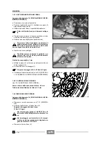
7.3.4 REASSEMBLY
Read 1.4 (PRECAUTIONS AND GENERAL INFORMA-
TION) carefully.
Insert the disc in the brake caliper with care.
X
Position the rear wheel between the tubes of the rear
fork.
X
Make the wheel advance and position the gearing
chain (1) on the crown gear (2).
Risk of injuries.
Do not use your fingers to align the seats.
X
Make the wheel move backwards and align the pin
seat on the wheel hub with the pin seats on the tubes
of the rear fork.
Grease the wheel pin, see p. 1.7 (LUBRICANT
CHART).
To facilitate the insertion of the wheel pin,
slightly raise the wheel.
X
Insert the wheel pin (3) complete with washer (4) from
the left side of the vehicle.
Make sure that the wheel pin has been insert-
ed completely.
X
Fit the washer (5) and screw the nut (6) completely.
X
Check the chain tension, see 2.16.1 (CLEARANCE
CONTROL).
X
Lock the wheel pin (3) rotation by means of the suita-
ble spanner and tighten the nut (6).
Wheel pin-nut (6-3) driving torque:
100 Nm (10 kgm).
Due to the weight and dimensions of the vehi-
cle, the following operation cannot be per-
formed by one person only.
Proceed with care and make sure that you can sup-
port the weight of the vehicle.
Weight of the vehicle without driver (ready for
starting): 200 kg.
X
Raise the rear part of the vehicle and remove the sup-
port positioned under the engine during the disassem-
bly.
X
Lower the vehicle and position it on the stand.
X
Correctly position the oil pan guard, see 7.1.9 (RE-
MOVING THE OIL PAN GUARD).
After reassembly, pull the rear brake lever re-
peatedly and check the correct functioning of
the braking system.
Check the centering and balancing of the wheel.
Summary of Contents for Pegaso 650
Page 1: ......
Page 3: ...0 4 NOTE NOTES ANMERKUNGEN ...
Page 4: ...1 1 1 2 3 4 5 6 7 8 INFORMAZIONI GENERALI INFORMACIONES GENERALES GENERAL INFORMATION ...
Page 42: ......
Page 69: ...3 1 1 2 3 4 5 6 7 8 MOTORE MOTOR ENGINE ...
Page 90: ...3 22 MOTORE NOTE NOTAS NOTES ...
Page 91: ...4 1 1 2 3 4 5 SISTEMA DI ALIMENTAZIONE SISTEMA DE ALIMENTACIÓN FUEL SYSTEM ...
Page 116: ...4 26 SISTEMA DI ALIMENTAZIONE NOTE NOTAS NOTES ...
Page 117: ...5 1 1 2 3 4 5 6 7 8 IMPIANTO DI RAFFREDDAMENTO SISTEMA DE REFRIGERACIÓN COOLING SYSTEM ...
Page 130: ...5 14 IMPIANTO DI RAFFREDDAMENTO SISTEMA DE REFRIGERACIÓN COOLING SYSTEM NOTE NOTAS NOTES ...
Page 131: ...6 1 6 1 2 3 4 5 6 7 8 IMPIANTO ELETTRICO INSTALACIÓN ELÉCTRICA ELECTRICAL SYSTEM ...
Page 176: ...IMPIANTO ELETTRICO INSTALACIÓN ELÉCTRICA ELECTRICAL SYSTEM 6 46 NOTE NOTAS NOTES ...
Page 177: ...7 1 1 2 3 4 5 6 7 8 CICLISTICA PARTE CICLO CHASSIS PARTS ...
Page 226: ... 67 3 57 2 66 6 3 576 7 50 5827 3267 5 25 58 75 6 5 5 5 ...
Page 242: ... 67 3 57 2 66 6 3 576 7 66 5 12 17 5 25 5 12 17 52 5217 5 ...
Page 246: ... 67 3 57 2 66 6 3 576 7 70 5 12 3267 5 25 5 12 75 6 52 5 5 5 ...
Page 272: ... 67 3 57 2 66 6 3 576 7 96 NOTE NOTAS NOTES ...
Page 311: ...INFORMAZIONI PER LE RIPARAZIONI INFORMACIONES PARA LAS REPARACIONES REPAIRS 8 39 ...

