7
- 91
3$57(&,&/2
&+$66,63$576
7.9.3 CONTROL
Controle que ningún componente esté defor-
mado, roto, con grietas y/o golpes evidentes.
Sustituya todos los componentes dañados.
COJINETES
X
Gire manualmente los rodillos, los cuales tienen que
girar suavemente, sin bloquearse ni hacer ruido.
No deben notarse desajustes.
Hay que sustituir los cojinetes que muestren tales in-
convenientes.
Engrase los rodillos, véase 1.7 (TABLA DE
LOS LUBRICANTES).
PERNO BASCULANTE
Con un comparador controle que la excentricidad del per-
no no supere el valor límite.
En caso contrario, sustituya el perno.
Excentricidad máxima del perno: 0,3 mm
Engrase el perno por toda su longitud, véase
1.7 (TABLA DE LOS LUBRICANTES).
7.9.4 INSTALACION
Lea con cuidado 1.4 (PRECAUCIONES E INFORMA-
CIONES GENERALES).
En la primera fase, el perno (1) la tuerca de
ajuste (2) y el casquillo de sujeción (3) tienen
que ser atornillados manualmente.
X
Inserte y atornille el perno (1) de sujeción bastidor/mo-
tor/basculante, manteniendo bloqueado la tuerca de
ajuste (2) y empleando la correspondiente llave tubu-
lar, véase 1.8 (EQUIPOS ESPECIALES).
X
Atornille la tuerca de ajuste (2) hasta llegar al tope so-
bre el basculante, luego atorníllelo aún de 1/4 de giro.
Apriete tuerca de ajuste (2): tope + 1/4 de giro
X
Manteniendo bloqueado la tuerca de ajuste (2), apriete
el perno del basculante (1).
Par de apriete perno (1): 100 Nm (10 kgm)
X
Vuelva a instalar la arandela.
X
Bloquee la tuerca de ajuste (2) y, a la vez, atornille el
casquillo de sujeción (3).
Par de apriete casquillo de sujeción (3):
100 Nm (10 kgm)
Desde este punto en adelante siga con la ins-
talación actuando en sentido contrario con
respecto al desmontaje, partiendo de la NOTA
(Y), véase 7.9.1 (DESMONTAJE).
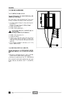
7.9.3 CHECKING
Make sure that none of the components
shows deformations, breaks, cracks and/or
evident dents.
Replace all the damaged components.
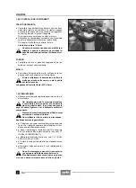
BEARINGS
X
Manually rotate the rollers, which must turn smoothly
and noiselessly.
No axial clearances should be noticed.
The bearings showing these defects must be changed.
Apply grease on the rollers, see 1.7 (LUBRI-
CANT CHART).
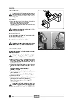
REAR FORK PIN
Using a comparator, make sure that the eccentricity of
the pin does not exceed the limit value.
Otherwise, change the pin.
Max. eccentricity of the pin: 0.3 mm.
Apply grease on the whole length of the pin,
see 1.7 (LUBRICANT CHART).
7.9.4 REASSEMBLY
Read 1.4 (PRECAUTIONS AND GENERAL INFORMA-
TION) carefully.
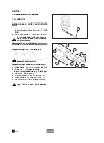
In the first phase, the pin (1), the adjusting bush (2)
and the lock ring (3) must be screwed by hand.
X
Introduce and screw the pin (1) that fastens frame,en-
gine and rear fork, holding the adjusting bush (2) by
means of the apposite socket spanner, see 1.8 (SPE-
CIAL TOOLS).
X
Screw the adjusting bush (2) until it reaches the end of
stroke on the rear fork, then give it another one fourth
turn.
Tightening of the adjusting bush (2):
c one fourth turn.
X
Hold the adjusting bush (2) and tighten the rear fork
pin (1).
Pin (1) driving torque: 100 Nm (10 kgm).
X
Put back the washer.
X
Lock the adjusting bush (2) and at the same time
screw the lock ring (3).
Lock ring (3) driving torque:
100 Nm (10 kgm).
From this point onwards, proceed with the re-
assembly starting from NOTE (Y), see 7.9.1
(REMOVAL) and following the reverse order
with respect to the removal.
Summary of Contents for Pegaso 650
Page 1: ......
Page 3: ...0 4 NOTE NOTES ANMERKUNGEN ...
Page 4: ...1 1 1 2 3 4 5 6 7 8 INFORMAZIONI GENERALI INFORMACIONES GENERALES GENERAL INFORMATION ...
Page 42: ......
Page 69: ...3 1 1 2 3 4 5 6 7 8 MOTORE MOTOR ENGINE ...
Page 90: ...3 22 MOTORE NOTE NOTAS NOTES ...
Page 91: ...4 1 1 2 3 4 5 SISTEMA DI ALIMENTAZIONE SISTEMA DE ALIMENTACIÓN FUEL SYSTEM ...
Page 116: ...4 26 SISTEMA DI ALIMENTAZIONE NOTE NOTAS NOTES ...
Page 117: ...5 1 1 2 3 4 5 6 7 8 IMPIANTO DI RAFFREDDAMENTO SISTEMA DE REFRIGERACIÓN COOLING SYSTEM ...
Page 130: ...5 14 IMPIANTO DI RAFFREDDAMENTO SISTEMA DE REFRIGERACIÓN COOLING SYSTEM NOTE NOTAS NOTES ...
Page 131: ...6 1 6 1 2 3 4 5 6 7 8 IMPIANTO ELETTRICO INSTALACIÓN ELÉCTRICA ELECTRICAL SYSTEM ...
Page 176: ...IMPIANTO ELETTRICO INSTALACIÓN ELÉCTRICA ELECTRICAL SYSTEM 6 46 NOTE NOTAS NOTES ...
Page 177: ...7 1 1 2 3 4 5 6 7 8 CICLISTICA PARTE CICLO CHASSIS PARTS ...
Page 226: ... 67 3 57 2 66 6 3 576 7 50 5827 3267 5 25 58 75 6 5 5 5 ...
Page 242: ... 67 3 57 2 66 6 3 576 7 66 5 12 17 5 25 5 12 17 52 5217 5 ...
Page 246: ... 67 3 57 2 66 6 3 576 7 70 5 12 3267 5 25 5 12 75 6 52 5 5 5 ...
Page 272: ... 67 3 57 2 66 6 3 576 7 96 NOTE NOTAS NOTES ...
Page 311: ...INFORMAZIONI PER LE RIPARAZIONI INFORMACIONES PARA LAS REPARACIONES REPAIRS 8 39 ...


