background image

15

use and maintenance   RSV mille - RSV mille R

+%9

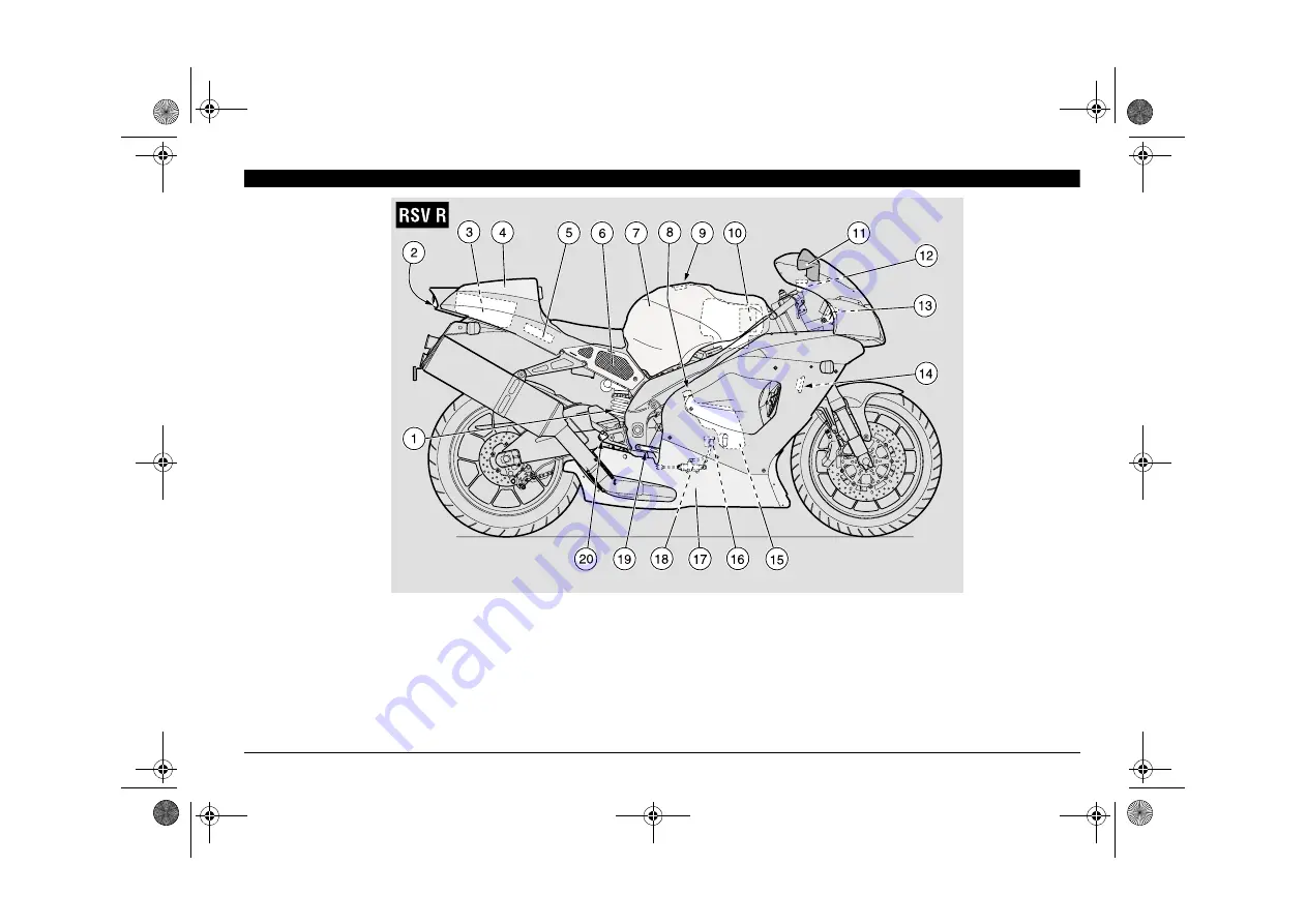
1) Rear shock absorber
2) Rear light
3) Glove/tool kit compartment
4) Glove/tool kit compartment 

cover 

5) Electronic unit 
6) Right side cover

7) Fuel tank
8) Coolant expansion tank

cap

9) Fuel tank filler cap

10) Air cleaner
11) Right rear-view mirror
12) Front brake fluid tank

13) Secondary fuse carrier 

(15A)

14) Horn
15) Expansion tank
16) Rear brake fluid tank
17) Lower fairing
18) Rear brake pump

19) Rear brake control lever
20) Rider right footrest 

RSVmille-R-UK.book  Page 15  Friday, November 17, 2000  3:13 PM

Summary of Contents for RST MILLE FUTURA - PART 1 2000

Page 1: ...RSVmille R UK book Page 1 Friday November 17 2000 3 13 PM ...

Page 2: ...ceded by this symbol must be repeated also on the opposite side of the vehicle If not expressly indicated otherwise for the reassembly of the units repeat the disas sembly operations in reverse order The terms right and left are referred to the rider seated on the vehicle in the nor mal riding position The vehicle w has been designed and produced as a single seater for the trans port of the rider ...

Page 3: ...spections The user of the vehicle in these countries must contact an aprilia Official Dealer to have the non homologated components re placed with others homologated for use in the country in question carry out the required periodical inspec tions NOTE Soon after purchasing the vehi cle write down the identification data indi cated on the SPARE PARTS IDENTIFICA TION LABEL in the table here below T...

Page 4: ...HEFT 58 MAINTENANCE 59 REGULAR SERVICE INTERVALS CHART 60 IDENTIFICATION DATA 62 CHECKING THE ENGINE OIL LEVEL AND TOPPING UP 62 CHANGING THE ENGINE OIL AND THE OIL FILTER 64 AIR CLEANER 66 ASSEMBLING THE PINS FOR THE REAR SUPPORT STAND m 67 POSITIONING THE VEHICLE ON THE REAR SUPPORT STAND m 67 POSITIONING THE VEHICLE ON THE FRONT SUPPORT STAND m 67 FRONT WHEEL 68 FRONT BRAKE CALIPERS 70 REAR WHE...

Page 5: ...RSVmille R UK book Page 5 Friday November 17 2000 3 13 PM ...

Page 6: ...eas with low traffic and or pri vate areas The use of medicins alcohol and drugs or psychotropic substances notably increases the risk of accidents Be sure that you are in good psychophysi cal conditions and fit for driving and pay particular attention to physical weariness and drowsiness Most road accidents are caused by the driver s lack of experience NEVER lend the vehicle to beginners and in a...

Page 7: ...o the road surface visibility and other driv ing conditions Avoid obstacles that could damage the ve hicle or make you lose control Avoid riding in the slipstream created by preceding vehicles in order to increase your speed Always drive with both hands on the han dlebars and both feet on the footrests or on the rider s footboards in the correct driving posture Avoid standing up or stretching your...

Page 8: ... acci dent make sure that no damage has oc curred to the control levers pipes wires braking system and vital parts If necessary have the vehicle inspected by an aprilia Official Dealer who should care fully check the frame handlebars suspen sions safety parts and all the devices that you cannot check by yourself Always remember to report any malfunc tion to the technicians to help them in their wo...

Page 9: ...aracteristics Never race with other vehicles Avoid off road driving 4 Before starting always wear a correctly fastened crash helmet Make sure that it is homologated in good shape of the right size and that the visor is clean Wear protective clothing preferably in light and or reflecting colours In this way you will make yourself more visible to the other drivers thus notably reducing the risk of b...

Page 10: ...n the vehicle may produce aerodynamic forc es that affect the stability of the vehicle es pecially when riding at high speed Make sure that the equipment is well fas tened to the vehicle and not dangerous during driving Do not install electrical devices and do not modify those already existing to avoid elec trical overloads because the vehicle could suddenly stop or there could be a danger ous cur...

Page 11: ...it people or obstacles making you lose control of the vehicle Do not carry any bag if it is not tightly se cured to the vehicle Do not carry bags which protrude too much from the luggage rack or which cover the lights horn or indicators Do not carry animals or children on the glove compartment or on the luggage rack Do not exceed the maximum load allowed for each side bag When the vehicle is overl...

Page 12: ...servoir 6 Left rear view mirror 7 Engine oil filter 8 Left side cover 9 Rider saddle 10 Battery 11 Main fuse carrier 30 A 12 Passenger seat lock 13 Passenger left footrest snapping closed open 14 Drive chain 15 Rear fork 16 Rider left footrest 17 Side stand 18 Shifting lever 19 Engine oil tank 20 Engine oil level 21 Engine oil tank cap RSVmille R UK book Page 12 Friday November 17 2000 3 13 PM ...

Page 13: ...assenger grab strap 7 Electronic unit 8 Right side cover 9 Fuel tank 10 Coolant expansion tank cap 11 Fuel tank filler cap 12 Air cleaner 13 Right rear view mirror 14 Front brake fluid tank 15 Secondary fuse carrier 15 A 16 Horn 17 Expansion tank 18 Rear brake fluid tank 19 Lower fairing 20 Rear brake pump 21 Rear brake control lever 22 Rider right footrest RSVmille R UK book Page 13 Friday Novemb...

Page 14: ...iring 6 Clutch fluid reservoir 7 Left rear view mirror 8 Left side cover 9 Rider saddle 10 Battery 11 Main fuse carrier 30A 12 Glove tool kit compartment lock 13 Drive chain 14 Rear fork 15 Rider left footrest 16 Side stand 17 Shifting lever 18 Engine oil filter 19 Engine oil tank 20 Engine oil level RSVmille R UK book Page 14 Friday November 17 2000 3 13 PM ...

Page 15: ...t side cover 7 Fuel tank 8 Coolant expansion tank cap 9 Fuel tank filler cap 10 Air cleaner 11 Right rear view mirror 12 Front brake fluid tank 13 Secondary fuse carrier 15A 14 Horn 15 Expansion tank 16 Rear brake fluid tank 17 Lower fairing 18 Rear brake pump 19 Rear brake control lever 20 Rider right footrest RSVmille R UK book Page 15 Friday November 17 2000 3 13 PM ...

Page 16: ...8 7 4 Direction indicator switch 6 5 Horn push button 6 Light switch not provided for e 7 High beam signaller push button 7 LAP push button multi function 8 Clutch lever 9 Instruments and indicators 10 Front brake lever 11 Throttle grip 12 Start push button 13 Engine stop switch 2 1 RSVmille R UK book Page 16 Friday November 17 2000 3 13 PM ...

Page 17: ...g light 6 Amber side stand down warning light Æ 7 Right multifunction digital display coolant temperature clock battery voltage chronometer diagnostic 8 Red engine oil pressure warning light LED 9 Green neutral indicator warning light 10 Multifunction computer programming push buttons 11 Left multifunction digital display speedometer odometer 3425 43 4 23 RSVmille R UK book Page 17 Friday November...

Page 18: ... possible see p 33 FUEL Side stand down warning light Æ Comes on when the side stand is down Engine oil pressure warning light LED Comes on whenever the ignition switch is in position 2 and the engine is not running thus checking the functionality of the LED If the light LED does not come on in this phase contact an aprilia Official Dealer If the engine oil pressure warning light LED remains on af...

Page 19: ... COOLANT If the writing is still displayed after the coolant level has been checked contact an aprilia Of ficial Dealer If the maximum allowed temperature 120 C 248 F is exceeded the engine may be serious ly damaged To alternate the data displayed see p 20 MUL TIFUNCTION COMPUTER Clock Indicates the hour and minutes according to the presetting see p 20 MULTI FUNCTION COMPUTER Battery voltage V BAT...

Page 20: ...on 6 and then the push button r and keep them pressed for about five seconds With the ignition key 1 in position 2 the standard settings on the dashboard are the following Right display Clock 7 coolant tempera ture in C 8 Left display Instantaneous speed in km h 9 trip 1 trip odometer 10 total kilometres miles odometer 11 Upon installation of the battery or of the 30A main fuses the revolution cou...

Page 21: ...the odometer set on the V max function press the push button r for about 2 sec onds NOTE The measurement of the maxi mum speed is relevant to the distance cov ered from the last setting to zero of the max imum speed itself The distance trip 1 10 shown on the display indicates the number of kilometres miles covered from the last setting to zero to the distance trip 1 To display the average speed 16...

Page 22: ...ng as j is kept pressed when it has reached the maximum value it starts again from the beginning Press the push button j until the de sired rpm value has been set If the push button j is released and then pressed again within 3 seconds intermit tently the pointer 4 moves increasing the value by 100 rpm at each click when it has reached the maximum value it starts again from the beginning NOTE It i...

Page 23: ...ng 8 appears on the right display aCAUTION If the writing is displayed with a temperature below 130 C 266 F there may be a failure of the electric circuit In this case contact an APRILIA Official Dealer Thermometer range on the display 35 130 C 95 266 F The digital clock 7 appears in the lower part of the right display To set or modify hour and minutes see p 24 SETTING THE HOUR and SETTING THE MIN...

Page 24: ... start blinking in the lower part of the right display digital clock To modify the minute setting press the LAP push button 6 on the left part of the handlebar To confirm the minute setting press the push button g SETTING C OR F When the push button g is pressed for the fourth time the segments of the cool ant temperature in C or F 8 start blinking in the upper part of the display To modify from C...

Page 25: ...be able to see the stored times in se quence press the LAP push button 6 The writings etc 26 are displayed To start timing again press the push but ton k NOTE It is possible to store max 40 times after which the LAP push button 6 is not effective any longer To set the memory to zero press the push button l and the LAP push but ton 6 at the same time for two seconds To leave the chronometer functio...

Page 26: ...light and the low beam are always on When it is in position the high beam comes on 4 LIGHT SWITCH not provided for e When the light switch is in position the lights are off when the switch is in position the parking lights and the dash board light are on when the switch is in position the parking lights the dashboard light and the low beam are on The high beam can be operated by means of the dimme...

Page 27: ...s in position 2 7 ENGINE STOP SWITCH 2 1 aWARNING Do not operate the engine stop switch 2 1 in run ning conditions This is a safety or emergency switch When the switch is in position 2 it is possible to start the engine the engine can be stopped by moving the switch to position 1 aCAUTION With stopped engine and ignition switch in position 2 the battery may discharge When the vehicle has come to r...

Page 28: ...onditions in order to avoid losing control of the vehicle OPERATION To lock the steering Turn the handlebar completely leftwards Turn the key to position 1 Press the key and rotate it to position Extract the key Position Function Key removal Steering lock The steer ing is locked It is neither pos sible to start the engine nor to switch on the lights It is possible to remove the key Neither the eng...

Page 29: ...b strap 3 Position the seat and press it making the lock snap aWARNING Before leaving make sure that the seat 2 is properly locked NOTE Upon request it is possible to supply the glove tool kit compartment cov er m 4 to be used instead of the passen ger seat If the glove tool kit compartment cover is used the passenger grab strap must be folded and put inside the glove tool kit compartment for the ...

Page 30: ...icient to release and re move the flap 3 NOTE Before lowering and locking the glove tool kit compartment cover 2 make sure that you have not left the key in the glove tool kit compartment To lock the glove tool kit compartment cover 2 Introduce the lower front projections in the relevant recesses on the rear part of the fairing Position the glove tool kit compartment cover in its seat and press it...

Page 31: ...rk spanner 3 11 13 mm double fork spanner 4 22 mm simple box spanner 5 32 mm simple box spanner 6 extension for simple box spanners 7 6 7 mm double socket spanner 8 8 10 mm double socket spanner 9 16 mm socket spanner for spark plug 10 double ended cross cut headed screw driver 11 tool case 12 Maximum allowed weight 1 5 kg 5 2 34 3 W Small luggage can be anchored to the pas senger seat by means of...

Page 32: ...plate holder extension 4 can be used when the road surface is wet in fact it reduces the reach of the water spray caused by the rear wheel NOTE The number plate holder exten sion 4 is supplied as standard component in the countries where this is required for the homologation Tool Operations Page Pins 1 for the rear support stand To position the vehicle on the rear support stand 62 Rear support sta...

Page 33: ...ll the tank to the brim Screw the plug up carefully after refuel ling Avoid any contact of the fuel with the skin and the inhalation of vapours do not swallow fuel or pour it from a re ceptacle into another by means of a tube DO NOT DISPOSE OF FUEL IN THE EN VIRONMENT KEEP AWAY FROM CHILDREN Use only premium grade unleaded petrol min O N 95 N O R M and 85 N O M M To refuel proceed as follows Raise...

Page 34: ... greasy especially after maintenance or checking operations Check that the brake cables are neither twisted nor worn out Prevent water or dust from accidentally getting into the circuit In case maintenance operations are to be performed on the hydraulic circuit it is advisable to use latex gloves If the brake fluid gets in contact with the skin or the eyes it can cause serious ir ritations aWARNIN...

Page 35: ...e braking system but is valid for both When the disc pads wear out the level of the fluid decreases to automatically com pensate for their wear The front brake fluid tank is positioned on the right part of the handlebar near the front brake lever coupling The rear brake reservoir is positioned un der the right fairing to reach it remove the right fairing see p 77 REMOVING THE SIDE FAIRINGS NOTE Pe...

Page 36: ...y prolonged exposure of the brake fluid to the air The brake fluid is hygroscopic and when in contact with the air it absorbs its humidity Leave the brake fluid tank open ONLY for the time necessary for topping up Raise and remove the cover 3 together with the screws 1 and the gasket 4 aCAUTION In order not to spill the brake fluid while topping up do not shake the vehicle Do not put additives or ...

Page 37: ...d to the air The brake fluid is hygroscopic and when in contact with the air it absorbs its humidity Leave the brake fluid tank open ONLY for the time necessary for topping up Unscrew the screw 3 completely Slightly move the whole reservoir 1 out wards Unscrew and remove the plug 2 aCAUTION In order not to spill the brake fluid while topping up keep the fluid in the tank parallel to the tank rim i...

Page 38: ...et in contact with the liquid Con sult a doctor or an oculist if the liquid gets in contact with your eyes DO NOT DISPOSE OF THE FLUID IN THE ENVIRONMENT KEEP AWAY FROM CHILDREN When using the fluid take care not to spill it on the plastic and painted parts since it damages them The clutch control fluid must be changed every two years by an APRILIA Official Dealer Use fluid of the type specified i...

Page 39: ... aCAUTION The fluid may flow out Do not operate the clutch control lever if the reservoir plug is loose or has been removed aWARNING Avoid any prolonged exposure of the clutch fluid to the air The clutch fluid is hygroscopic and when in contact with the air it absorbs its hu midity Leave the clutch fluid tank open ONLY for the time necessary for topping up Unscrew and remove the plug 2 aCAUTION Do...

Page 40: ... and send out invisible flames In case any maintenance operation should be required it is advisable to use latex gloves aCAUTION Have the pads changed by your APRILIA Official Dealer The coolant is composed of 50 water and 50 antifreeze This mixture is ideal for most running tem peratures and ensures good protection against corrosion It is advisable to keep the same mixture also in the hot season ...

Page 41: ...ow it if the coolant gets in contact with the skin or the eyes it can cause serious ir ritations Do not use your fingers or any other ob ject to check if there is enough coolant aCAUTION Do not put additives or other subtances into the fluid If you use a funnel or other similar items make sure that they are perfectly clean Top up the expansion tank by adding coolant see p 113 LUBRICANT CHART until...

Page 42: ...icle are provided with wear indi cators There are several kinds of wear indica tors For more information on how to check the wear contact your Dealer Visually check if the tyres are worn and in this case have them changed Change the tyre when it is worn out or in case of puncture on the tread side if the puncture is larger than 5 mm After repairing a tyre have the wheels balanced aWARNING The tyre...

Page 43: ...e engine this means that the engine oil pressure in the circuit is insufficient In this case check the engine oil level see p 62 CHECKING THE ENGINE OIL LEVEL AND TOPPING UP if the level isn t correct stop the engine immedi ately and contact an APRILIA Official Dealer aCAUTION Proceed with care Do not spill the oil Take care not to smear any component the area in which you are working and the surr...

Page 44: ...f the vehi cle If necessary it is possible to adjust the brake control lever clearance Remove the lower fairing see p 77 RE MOVING THE LOWER FAIRING Loosen the lock nut 4 Unscrew the pump control rod 5 to en sure a minimum clearance of 0 5 1 mm between the rod and the pump piston aCAUTION Make sure that there is a certain idle stroke in the movement of the lever 6 to prevent the brake from remaini...

Page 45: ...can be switched off only by turn ing the ignition switch to position 1 Before starting the vehicle make sure that the dimmer switch is in position 8 front low beam 8 534 3 2 8 534 4 2 aWARNING Tampering with the noise control sys tem is prohibited Owners are warned that the law may pro hibit the removal or rendering inoperative by any person other than for purposes of maintenance repair or replace...

Page 46: ...Do not apply the load of your weight or of the passenger s weight onto the side stand The stand has been designed to support the weight of the vehicle and a minimum load without the rider and the passenger Getting on the vehicle into the riding posi tion with extended side stand is permitted only for the purpose of preventing the vehi cle from falling or overturning and does not envision the loadi...

Page 47: ...traighten the vehicle into riding position while keeping it in balance NOTE The rider must not extract or at tempt to extract the passenger footrest while seated astride the vehicle because this might compromise the stability and bal ance of the vehicle Have the passenger extract the two pas senger footrests Instruct the passenger how to safely get on the vehicle Kick the side stand completely bac...

Page 48: ...he electronic unit Whenever the ignition switch is brought to position 2 the writing HIL 1 appears on the right side of the multifunction display for approximately three seconds aCAUTION If the writing HIL 1 is displayed during the normal operation of the en gine this means that the electronic unit has detected an anomaly In many cases the engine keeps run ning with reduced performance levels imme...

Page 49: ...the fluid the clutch must operate without jerking and or slipping 38 39 Steering Make sure that the steering rotates smoothly without any clearance or slackening Side stand Make sure that it operates correctly Make sure that when the stand is let up or down there is no friction and that the spring tension brings it back to its normal position If necessary lubricate joints and hinges Make sure that...

Page 50: ... THE VE HICLE Make sure that the stand is completely up Not provided for e Make sure that the light switch 1 is in position Make sure that the dimmer switch 2 is in position 8 Move the engine stop switch 3 to posi tion 2 Rotate the key 4 and move the ignition switch to position 2 At this point The engine oil pressure LED warning light red 5 comes on on the dashboard and remains on until the engine...

Page 51: ...ttery do not keep the start push but ton pressed for more than fifteen seconds If the engine does not start in this lapse of time wait ten seconds and press the start push button again Press the start push button 18 with out accelerating and release it as soon as the engine starts aCAUTION Avoid pressing the start push button 18 when the engine is running since you may damage the starter If the en...

Page 52: ...om temperature is low near to or lower than 0 C 32 F it may be difficult to start the vehicle at the first attempt In this case Rotate the cold start lever 0 17 down wards Insist for at least ten seconds with the start push button 18 pressed and at the same time moderately rotate the throttle grip 19 If the engine starts Release the start push button 18 and the throttle grip 19 Rotate the cold sta...

Page 53: ... your hands on the grips and your feet on the footrests NEVER RIDE IN ANY POSITION OTHER THAN THOSE INDICATED aWARNING If you drive with a passenger instruct him her so that he she does not create problems during manouvres Before leaving make sure that the stand is completely up To leave Start the engine see p 50 STARTING Adjust the inclination of the rear view mirrors correctly aCAUTION With the ...

Page 54: ...ow rpm Release the throttle grip 2 Pos A pull the clutch lever 3 and lift the shifting le ver 4 Release the clutch lever 3 and accelerate Repeat the last two operations and shift up aCAUTION If the engine oil pressure warning light LED 5 comes on during the nor mal operation of the engine this means that the engine oil pressure in the cir cuit is insufficient In this case stop the engine immediate...

Page 55: ...ng with vehicle at rest engaged gears and pulled clutch lever for the shortest possible time aWARNING Avoid opening and closing the throttle grip repeatedly and continuously so that you do not accidentally lose control of the vehicle If you have to brake close the throttle and put on both brakes in order to obtain uniform decel eration properly exerting pressure on the braking parts By putting on ...

Page 56: ...important to stress the engine components during running in take care not to exceed NOTE Only after the first 1500 km 937 mi of running in you can expect the best performance levels from the vehicle Keep to the following indications Do not open the throttle completely if the speed is low both during and after the running in During the first 100 km 62 mi put on the brakes with caution avoiding shar...

Page 57: ... danger for persons and children Do not leave the vehicle unattended when the engine is on or the key is inserted into the ignition switch Do not get too near the cooling fans even if they are still since they may start moving and suck clothes edges hair etc aWARNING The fall or excessive inclination of the vehicle may cause the fuel to flow out of the tank The fuel used for internal combustion en...

Page 58: ...end it completely 3 Incline the vehicle until the stand rests on the ground Steer the handlebar completely left wards aWARNING Make sure that the vehicle is stable 35 34 3 4 02 6 4 4 4 NEVER leave the ignition key inserted and always use the steering lock Park the vehicle in a safe place possibly in a garage or a protected place When possible use an additional anti theft device Make sure that all ...

Reviews: