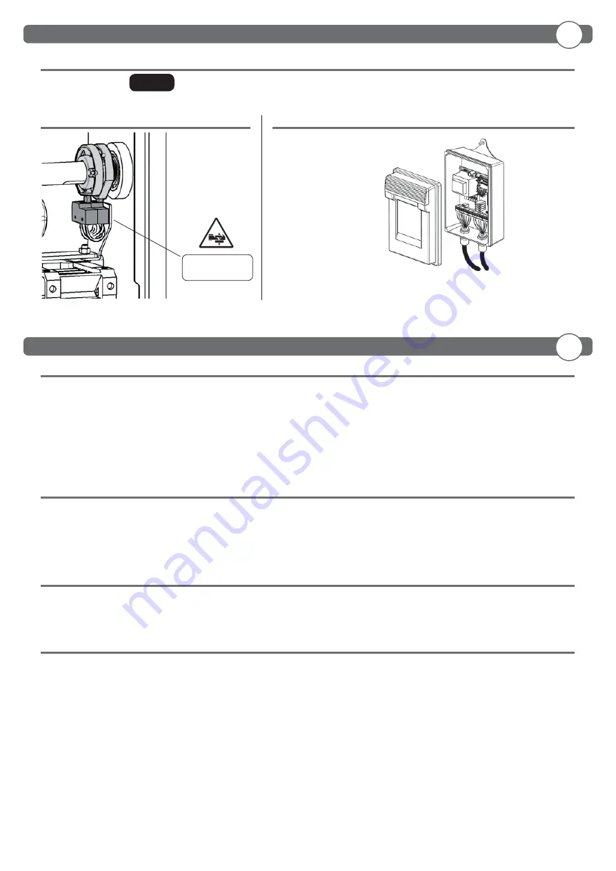
background image

- 11 -

ADDITIONAL 

LIMIT SWITCH

Consult the


control unit’s installation 

and operating manual 

2.7 OPTIONALS

2.8 ELECTRICAL CONNECTIONS

For balancing the bar see 


ND.3

 pag. 24

2.6 BALANCING THE ARM

3.1 GENERAL SAFETY

• The barrier is designed exclusively for vehicles traffi

  c; report and delimit any walkways through a special sign. 

• Keep adults, children and property out of range of the automated system, especially while it is operating.
• For safety reasons and to comply with current standards, we recommend using the control unit.
• To install follow the instructions given in the enclosed “GENERAL INSTRUCTIONS FOR SAFETY” sheet.
• All electrical connections must be done in compliance with current laws.
• The installer must instruct the user on how to use the automatism correctly, on the manual emergency manoeuvre and on the possible risks during operation.
• Analyse the risks and take all the appropriate measures to eliminate them, as prescribed by the EEC machine directive 2006/42, installing the safety devices.

• Always disconnect the electricity before attempting any work on the system with a lockable cut-off

  switch.

3.2 WARNINGS

Correct controller operation is only ensured when the data contained in the present manual are observed. The Company is not to be held responsible 
for any damage resulting from failure to observe the installation standards and the instructions contained in the present manual.
The descriptions and illustrations contained in the present manual are not binding. The Company reserves the right to make any alterations 
deemed appropriate for the technical, manufacturing and commercial improvement of the product, while leaving the essential product features 
unchanged, at any time and without undertaking to update the present publication.

3.3 USE

• It is essential to follow the instructions given in the enclosed “GENERAL INSTRUCTIONS FOR SAFETY” sheet.
• In the case of a manual emergency manoeuvre, follow the indications described in point 2.5.
• Consult the control unit’s installation and operating manual. 

3.4 ROUTINE MAINTENANCE

 (EVERY 6 MONTHS)

• Maintenance must be carried out by qualifi

 ed personnel only.

• Check the condition of the barrier structure.
• Check tightness of the arm.
• Check the condition of the spring, chain and relative anchorings. 
• Check arm balance.
• Check that at the end of travel the arm is horizontal and/or vertical
• Check operation of the manual emergency manoeuvre.
• Check operation of the control unit and safety devices. 

EN

EN

2. Installation

3. Use and maintenance

TRAFFIC 

PARK 230

Summary of Contents for PARK 30 PLUS

Page 1: ...tion use and maintenance Instructions d installation et d entretien Installations Gebrauchs und Wartungsanleitungen Instrucciones para la instalaci n el uso y el mantenimiento Barriera automatica Auto...

Page 2: ......

Page 3: ...les pag 13 2 2 Fixation structure pag 13 2 3 Installation de la lisse pag 14 2 4 Alignement de la lisse pag 14 2 5 Manoeuvre manuelle pag 14 2 6 Equilibrage de la lisse pag 15 2 7 Optionals pag 15 2 8...

Page 4: ...le con soglia da 0 03A Applicare tutti i dispositivi di sicurezza fotocellule coste sensibili ecc necessari a proteggere l area da pericoli di schiacciamento convogliamento cesoiamento secondo ed in c...

Page 5: ...e la dima prima del fissaggio della barriera 19 mm 13 mm Non fornito 1 Linea Monofase 2 x 1 5 T 2 FotocellulaTrasmittente 2 x 0 5 3 Fotocellula Ricevente 4 x 0 5 4 Selettore a chiave 3 x 0 5 5 Riceven...

Page 6: ...are il portabarra PER ALLINEARE LA BARRA ALLA PAVIMENTAZIONE STRADALE AGIRE SUL PORTABARRA REGOLABILE NON MODIFICARE LA POSIZIONE DEI FINECORSA GIA PRETARATI 2 5 MANOVRA MANUALE Sbloccaggio manuale EF...

Page 7: ...ionatore 3 2 AVVERTENZE Ilbuonfunzionamentodell automazione garantitosolosevengonorispettateidatiriportatiinquestomanuale LaDittanonrispondedeidanni causati dall inosservanza delle norme di installazi...

Page 8: ...a differential switch with a 0 03A threshold is fitted just before the power supply mains Fit all the safety devices photocells electric edges etc which are needed to protect the area from any danger...

Page 9: ...TRUCTURE We advise removing the template before fixing the barrier 19 mm 13 mm Not supplied 1 Single phase line 2 x 1 5 T 2 Transmitter photocell 2 x 0 5 3 Receiver photocell 4 x 0 5 4 Key selector 3...

Page 10: ...mand to position the arm holder horizontally To regulate the adjustable arm holder 2 5 MANUAL MANEUVER Always disconnect the electricity before attempting any work on the system USE THE ADJUSTABLE ARM...

Page 11: ...edwhenthedatacontainedinthepresentmanualareobserved TheCompanyisnottobeheldresponsible for any damage resulting from failure to observe the installation standards and the instructions contained in the...

Page 12: ...tation il y a un interrupteur diff rentiel avec seuil de 0 03A Appliquer tous les dispositifs de s curit cellules photo lectriques barres palpeuses etc n cessaires prot ger la zone des dangers d crase...

Page 13: ...URE Il est recommand de retirer la plaque avant de fixer la barri re 19 mm 13 mm Non fourni 1 Ligne monophas e 2 x 1 5 T 2 Photocellule mettrice 2 x 0 5 3 Photocellule r ceptrice 4 x 0 5 4 S lecteur c...

Page 14: ...onnezlacommande START pourplacerlesupportdelisse en position horizontale R glez le support de lisse POUR ALIGNER LA LISSE PAR RAPPORT LA CHAUSS E INTERVENIR SUR LE SUPPORT DE LISSE R GLABLE NE PAS MOD...

Page 15: ...AVERTISSEMENTS Le bon fonctionnement de l actionneur n est assur que si les donn es fournies dans ce manuel sont respect es Le constructeur ne r pond pas pour les dommages provoqu s par le non respect...

Page 16: ...tandvonmindestens 3 5 mm Der Versorgungsleitung mu ein Fehlerstromschutzschalter mit einer Schwelle von 0 03A vorgeschaltet sein Alle Sicherheitsvorrichtungen Fotozellen Sicherheitsleisten u a anbring...

Page 17: ...RBEFESTIGUNG Wir empfehlen die Schablone zu entfernen bevor die Schranke befestigt wird 19 mm 13 mm Nicht mitgeliefert 1 Einphasenleitung 2 x 1 5 T 2 Senderfotozelle 2 x 0 5 3 Empf ngerfotozelle 4 x 0...

Page 18: ...h anschlie en siehe Punkt 2 8 Den Befehl START eingeben um Die Schrankenhalterung in die waag rechte Position bringen Die Schranke montieren und die Schrankenhalterung einstellen ZUM AUSRICHTEN DER SC...

Page 19: ...g mit einen Schl ssel Trennschalter zu unterbrechen 3 2 HINWEISE Der einwandfreie Betrieb des Antriebes ist nur dann garantiert wenn die Angaben aus diesem Handbuch beachtet werden Der Hersteller haft...

Page 20: ...ificar que antes de la red de alimentaci n haya un interruptor diferencial con un umbral de 0 03A Aplicar todos los dispositivos de seguridad fotoc lulas barras sensibles etc necesarios para proteger...

Page 21: ...RUCTURA Aconsejamos quitar la plantilla antes de fijar la barrera 19 mm 13 mm No suministrada 1 L nea monof sica 2 x 1 5 T 2 Fotoc lula transmisor 2 x 0 5 3 Fotoc lula receptor 4 x 0 5 4 Selector de l...

Page 22: ...Dar el comando START para colocar el portabarra en posi ci n horizontal Instalar la barra y ajustar el portabarra PARA ALINEAR LA BARRA CON LA CALZADA ACTUAR SOBRE EL PORTABARRA REGULABLE NO MODIFICA...

Page 23: ...onamiento del operador resulta garantizado nicamente si se respetan los datos contenidos en este manual de instrucciones La empresa no responde de los da os causados por el incumplimiento de las norma...

Page 24: ...ATIVOS Controllare che la barra sia equilibrata a 45 Check that the arm is balanced at 45 S assurer que la lisse est quilibr e 45 berpr fen dass die Schranke in der 45 Stellung ausgeglichen ist Compro...

Page 25: ...25...

Page 26: ...ervention description Firma Signature 1 Tecnico Technician Cliente Customer 2 Tecnico Technician Cliente Customer 3 Tecnico Technician Cliente Customer 4 Tecnico Technician Cliente Customer 5 Tecnico...

Page 27: ...27...

Page 28: ...INSTALLATORE INSTALLER INSTALLATEUR INSTALLATEUR INSTALADOR...

Reviews:

Related manuals for PARK 30 PLUS