- 29 -
ES
ESPAÑOL
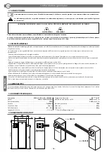
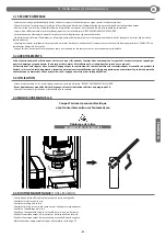
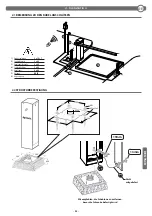
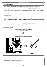
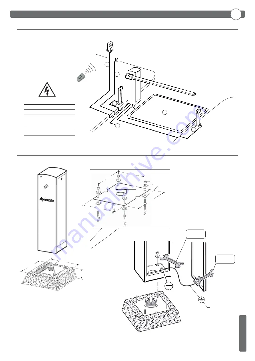
2.1 NOTA CABLES
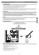
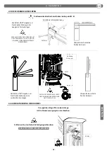
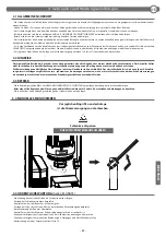
Aconsejamos quitar la plantilla antes
de fi jar la barrera
19mm
13mm
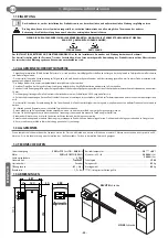
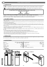
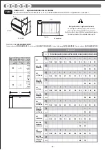
No
suministrada
1)
Línea monofásica
2 x 1,5 + T
2)
Fotocélula transmisor
2 x 0,5
3)
Fotocélula receptor
4 x 0,5
4)
Selector de llave
3 x 0,5
5)
Receptor
4 x 0,5
5)
Antena
RG58
6)
Espiral magnética
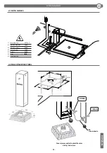
M12
Ø12x35x5
200
200
250
280
Ø100
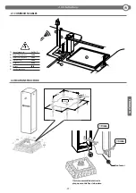
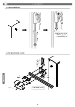
2. Instalaci
ó
n
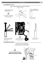
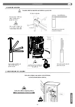
2.2 FIJACIÓN ESTRUCTURA
500
500
400
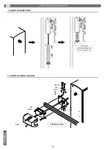
5
6
3
1
2
4
Summary of Contents for PARK 30 XT
Page 2: ......


