

41
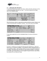
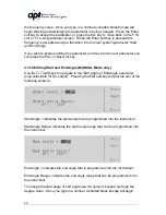
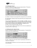
4.3 Editing System Parameters
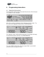
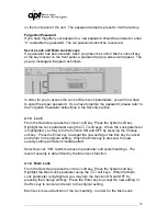
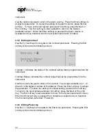
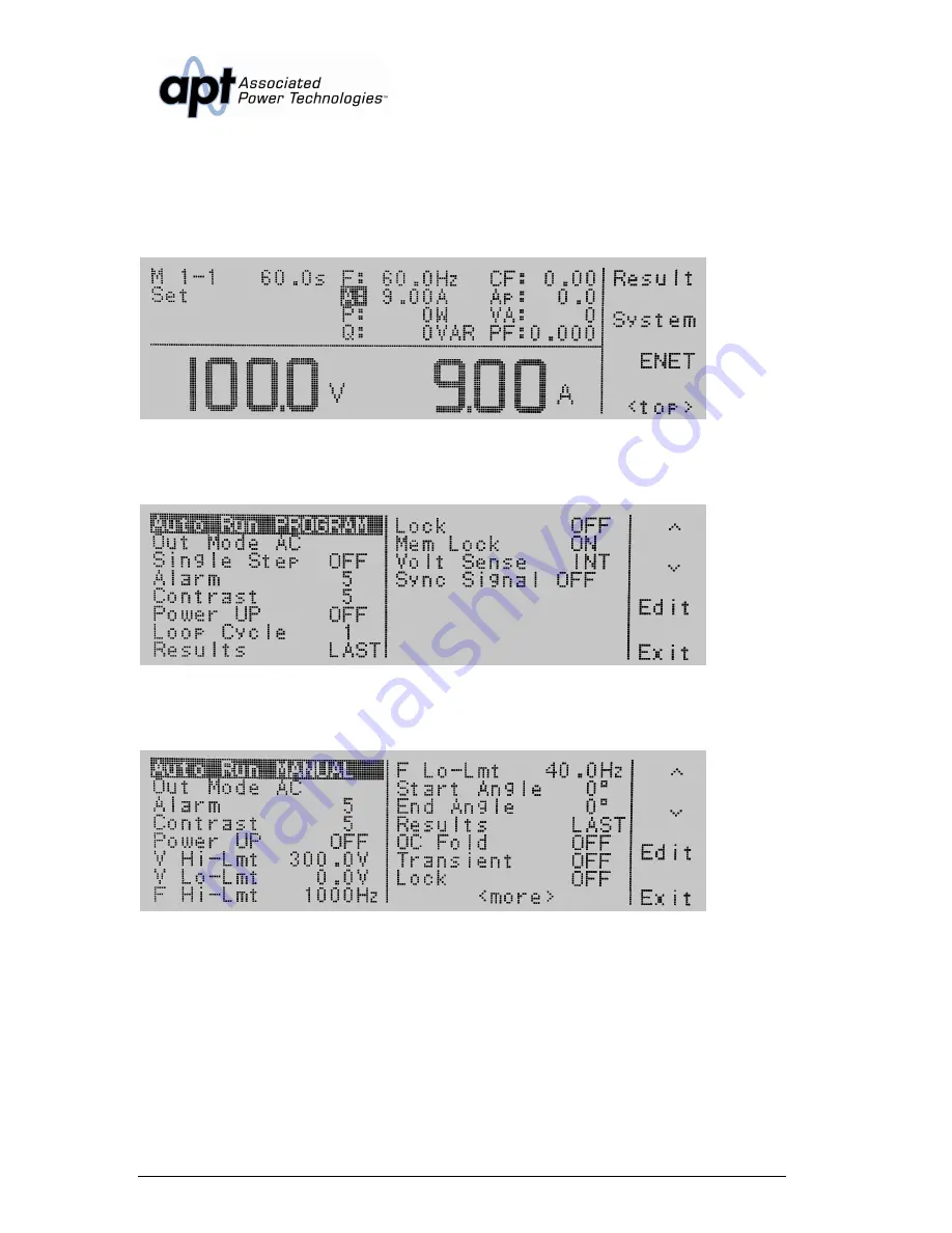
To edit System parameters press the <more> soft key from the set screen so the
soft keys read Result, System, and <top>. The screen should be as follows
when in PROGRAM Mode.
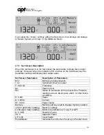
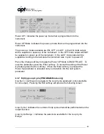
When the System soft key is pressed the system parameter screen will open and
show all the parameters available for editing. The screen will look as follows:
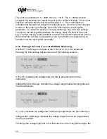
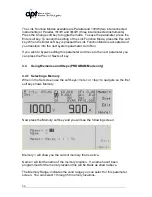
If the system parameters are set to MANUAL Mode, the screen will look as
follows:
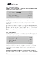
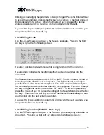
Use the
∧
,
∨
soft keys to navigate through the System parameters. Press the
Edit soft key to select the parameter. The parameter will be highlighted black if it
is available for editing. Press the Edit soft key to open up the system parameter
for editing. The Exit soft key will return you back to the set screen. If you open
any System parameter screen you can navigate through the System parameters
by using the Prev and Next soft keys.
Summary of Contents for 310XAC
Page 13: ...13 320XAC 340XAC...
Page 116: ...116 1 Test Complete OK WAI Wait for next command...


