background image

BACK

PANEL

CONTROLS

2.

1.    

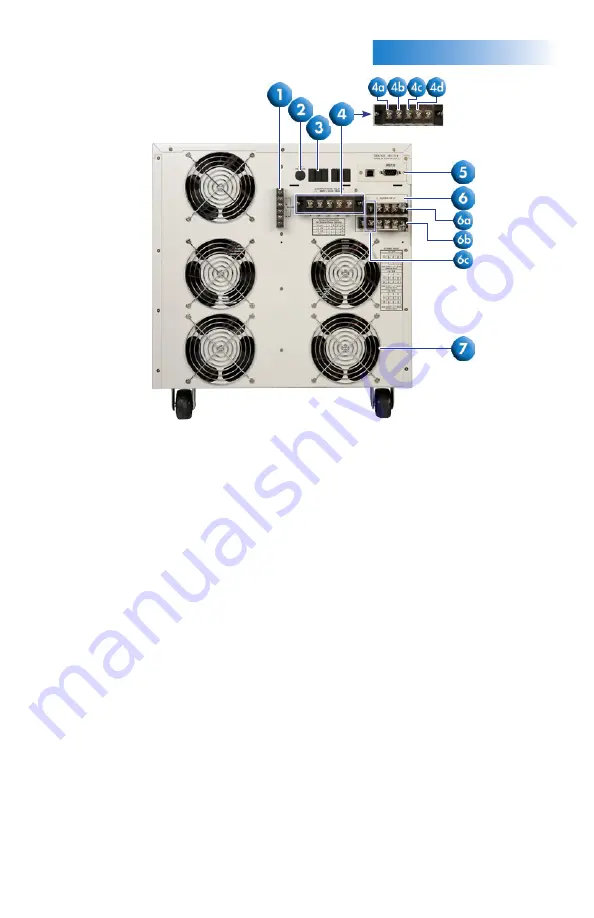
 EXTERNAL SENSE OUTPUT TERMINAL BLOCK:

 Provides screw terminals for external 

voltage sense leads.

2.    

EXTERNAL TRIGGER CONNECTOR:

 Provides the capability to monitor a 5 VDC 

output signal.

3.    

REMOTE OUTPUT CONNECTOR:

 Provides output to monitor PASS, FAIL, TEST-IN-

PROCESS via relay contact closures

4.  

OUTPUT TERMINAL POWER BLOCK:

 Provides output power to the DUT.

   4a.

 Phase A for 3Ø4W output mode


4b.

 Phase B for 3Ø4W output mode


4c.

 Phase C for 3Ø4W output mode


4d.

 Neutral terminal

5.


 USB/RS-232/GPIB INTERFACE CARD:

 Interface card used to control, program, and 

capture data.

6. 

  INPUT TERMINAL POWER BLOCK:

 Provides input power to the instrument. Model 

430XAC requires 200-240 VAC, 1Ø, 47-63 Hz. Model 460XAC requires 1Ø: 

200~240 VAC, 3Ø3W: 200~240 VAC, 3Ø4W: 346~416 VAC.


6a. 

N: Neutral input screw terminal.


6b.

 L: Line input screw terminal.


6c .

 G: Earth ground (chassis) connection.

7.  

  THERMAL  FAN:

 Used to cool the instrument.

Note:

 Model 430XAC has one input bar as opposed to two bars shown on the 460XAC.

(460XAC Back Panel)

Summary of Contents for 400XAC Series

Page 1: ...E SURE to use the appropriate AWG for your input and output cabling TURN OFF the output when making any connections to the load WARNING THIS GUIDE WAS CREATED FOR OPERATORS HAVING SOME FAMILIARITY WIT...

Page 2: ...just the voltage frequency output in MANUAL Mode or DC Mode 6 TEST RESET LED When lit this LED indicates output is active or when blinking indicates the instrument is in a failure condition 7 TEST RES...

Page 3: ...ode 4b Phase B for 3 4W output mode 4c Phase C for 3 4W output mode 4d Neutral terminal 5 USB RS 232 GPIB INTERFACE CARD Interface card used to control program and capture data 6 INPUT TERMINAL POWER...

Page 4: ...and memories allowing the operator to quickly run a test with basic test parameters 1 Turn the instrument power switch ON 2 From the Set screen press the more soft key and press SYSTEM in the next sc...

Page 5: ...load Press EDIT from the Set screen Use the up and down arrow soft keys to highlight the A Hi Lmt parameter Press EDIT to change the parameter Use the Numeric Keypad to enter the desired current limi...

Page 6: ...figures below illustrate how the 400XAC can be fully configured for an automated test setup Figure 3 3 4W Configuration Figure 4 3 3W Configuration Figure 5 1 2W Configuration A A Line Neutral Load L...

Page 7: ...APPLICATIONCONFIGURATIONS 6 Figure 6 1 3W Configuration Figure 7 DC Output Configuration DC Line 1 Line 2 Load Load DC Neutral...

Page 8: ...aptsources com 400XAC 10 13 VIEWINGTESTRESULTS From the Set screen press the RESULTS key to view the results If you have multiple steps linked together you will have to use the up and down arrow soft...

Reviews: