background image

3.

CHANGING

TEST

MODES

        WARNING: 

LOCATE A SUITABLE TESTING AREA WITH A THREE-PRONG, GROUNDED OUTLET.  BE 

SURE THAT THE THREE PRONG GROUNDED OUTLET HAS BEEN TESTED FOR PROPER WIRING.  MAKE SURE YOU 
READ THE SAFETY CHECKLIST OF THIS GUIDE BEFORE USING THE INSTRUMENT.

The 400XAC includes two test modes that change the way in which the AC power source 
operates. PROGRAM mode allows the operator to configure and run a test using steps and 
memory locations within the AC power source’s menu. PROGRAM mode is designed for 
advanced testing applications. MANUAL mode doesn’t utilize steps and memories, allowing 
the operator to quickly run a test with basic test parameters.

1.Turn the instrument power switch ON.  

2.  From the Set screen, press the “<more>” soft key and press SYSTEM in the next screen.

3.  In the System Parameters Menu, use the up or down arrow soft keys to highlight the  

AUTO RUN parameter. Press EDIT to change the parameter.

4.  Press CHANGE to toggle the parameter between PROGRAM and MANUAL mode. Press 

ENTER to save changes and then press EXIT to return to the Set screen.

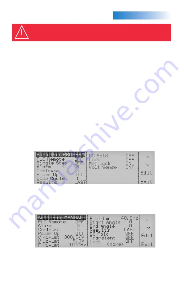
When the AUTO RUN parameter is set to PROGRAM mode, the Set screen will be displayed 
as follows: (See Figure 1)

When the AUTO RUN parameter is set to MANUAL mode, the Set screen will be displayed 
as follows: (See Figure 2)

(Figure 1. System Parameters Menu)

(Figure 2. System Parameters Menu)

Summary of Contents for 400XAC Series

Page 1: ...E SURE to use the appropriate AWG for your input and output cabling TURN OFF the output when making any connections to the load WARNING THIS GUIDE WAS CREATED FOR OPERATORS HAVING SOME FAMILIARITY WIT...

Page 2: ...just the voltage frequency output in MANUAL Mode or DC Mode 6 TEST RESET LED When lit this LED indicates output is active or when blinking indicates the instrument is in a failure condition 7 TEST RES...

Page 3: ...ode 4b Phase B for 3 4W output mode 4c Phase C for 3 4W output mode 4d Neutral terminal 5 USB RS 232 GPIB INTERFACE CARD Interface card used to control program and capture data 6 INPUT TERMINAL POWER...

Page 4: ...and memories allowing the operator to quickly run a test with basic test parameters 1 Turn the instrument power switch ON 2 From the Set screen press the more soft key and press SYSTEM in the next sc...

Page 5: ...load Press EDIT from the Set screen Use the up and down arrow soft keys to highlight the A Hi Lmt parameter Press EDIT to change the parameter Use the Numeric Keypad to enter the desired current limi...

Page 6: ...figures below illustrate how the 400XAC can be fully configured for an automated test setup Figure 3 3 4W Configuration Figure 4 3 3W Configuration Figure 5 1 2W Configuration A A Line Neutral Load L...

Page 7: ...APPLICATIONCONFIGURATIONS 6 Figure 6 1 3W Configuration Figure 7 DC Output Configuration DC Line 1 Line 2 Load Load DC Neutral...

Page 8: ...aptsources com 400XAC 10 13 VIEWINGTESTRESULTS From the Set screen press the RESULTS key to view the results If you have multiple steps linked together you will have to use the up and down arrow soft...

Reviews: