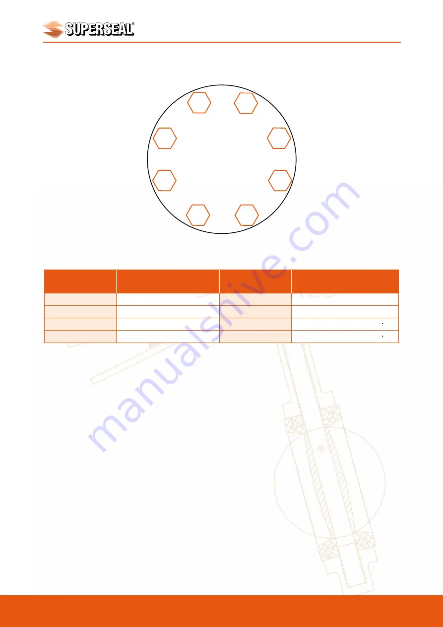
Do not exceed double the torques shown for 50 NB to 300 NB. For 350 NB to 400 NB do not exceed more than torques
shown by more than 50%. Bolting torques can vary. We recommend bolts are pregreased to increase strength and life.
The above torques are minimum torques. The profile and resilience of the liner will effect the torque. Only use high
tensile bolts.
4 . 0 I N S T A L L A T I O N W I T H
F L A N G E W E L D I N G
When butterfly valves are to be installed between welding type flanges care should be taken to abide by
the following procedure to ensure no damage will occur to the soft seat. To ensure no damage to the
seat, insert the valve between the flanges after welding.
1. Place the valve between the flanges with the flange bores and valve body aligned properly. The disc
should be in the 10
°
open position.
2. Span the body with the bolts.
3. Take this assembly of the flange-body-flange and align it properly to the pipe.
4. Tack weld the cut off flanges to the pipe.
5. Weld the flanges.
6. Install the valve once flanges have cooled.
Australian Pipeline Valve - Installation, Operation and Maintenance Manual
9
LINED BUTTERFLY VALVES - MODEL 2014 & 2016 SERIES
Flange Size
Recommended Min.
Bolt Torque
Flange Size
Recommended Min.
Bolt Torque
50 - 100 NB (2 - 4")
27.1 - 40.6 NM (20 - 30 ft·lbs.)
350 - 400 NB (14 - 16") 189.8 - 271.1 NM (140 - 200 ft·lbs.)
150 - 200 NB (6 - 8")
44.7 - 67.7 NM (33 - 50 ft·lbs.)
450 - 500 NB (18 - 20") 203.3 - 248.7 NM (150 - 210 ft·lbs.)
250 NB (10")
71.8 - 101.6 NM (53 - 75 ft·lbs.)
600 - 750 NB (24 - 30") 291.5 - 406.7 NM (215 - 300 ft lbs.)
300 NB (12")
108.4 - 149.1 NM (80 - 110 ft·lbs.) 900 NB (36")
406.7 - 508.4 NM (300 - 375 ft lbs.)
MINIMUM RECOMMENDED BOLTING TORQUE
FIGURE 8 - MINIMUM RECOMMENDED BOLTING TORQUE
1
7
4
5
3
8
2
6
FIGURE 7 - RECOMMENDED BOLT TIGHTENING SEQUENCES
Example only, same, criss-cross pattern applies for all bolting patterns.


