background image

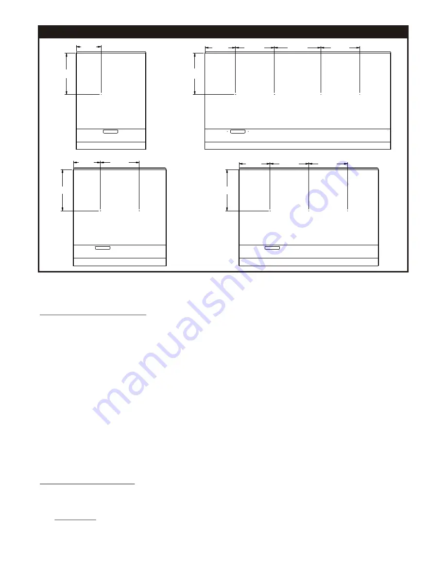
GGT CALIBRATION PROBE LOCATION

6.422

10.645

GGT-18

GGT-24

10.645

6.925

10.000

GGT-36

10.645

7.925

10.000

10.000

GGT-48

10.645

7.844

10.000

12.000

10.000

CALIBRATION PROCEDURE FOR GGT GRIDDLES

Locate the reading positions


Make sure the griddle surface is clean. Grease or food particles on the griddle will result in inaccurate 
thermostat calibration. 

Mark the locations where the temperature probe will be placed for testing. See the sketch provided. Starting 
from the left side of the griddle measure 8” to the right and 10-5/8” from the rear splash guard. With a felt tip 
pen mark this location. This is the location directly over the center of the left thermostat bulb. From this point 
measure right 10” remaining 10-5/8” from the rear splash guard. Mark this location with a felt tip pin. This is 
the location over the next thermostat bulb. For a 36” GGT repeat this one more time 10” to the right and for 
the 48” GGT repeat this twice more 10” to the right always remaining 10-5/8” from the splash guard. After all 
locations are marked 

center the temperature probe on each marked location, 

and then trace a circle 

around the probe. 

This procedure will place the temperature probe over the center of each thermostat bulb, and this is the only 
place temperature readings should be taken. 

Set all thermostats to 350ºF and allow them to cycle three to four times, or allow the griddle to preheat for ½ 
hour before proceeding. This makes sure the griddle temperatures have saturated the surface. 

Determine the differential

Note the temperature for each section of the griddle as the burners ignite. 
Note the temperature for each section of the griddle as the flame extinguishes. 
The flame extinguish temperature minus the ignition temperature equals the differential. 

       EXAMPLE: 


Flame extinguished 367ºF       
Flame ignition 341ºF       
Difference 26º F = Differential

9

Summary of Contents for Champion GGM-18H

Page 1: ...umber Serial Number Date Purchased Gas Griddles MODELS GGT 18H 24H 36H 48H MODELS GGM 18H 24H 36H 48H WARNING Improper installation operation service or maintenance can cause property damage injury or...

Page 2: ...al shutoff valve to be supplied by user must be disconnected from the gas supply piping system during any pressure testing of that system at test pressures in excess of psi 3 45 kPa The appliance must...

Page 3: ...result in serious injury or death DANGER This symbol warns of imminent hazard which will result in serious injury or death CAUTION This symbol refers to a potential hazard or unsafe practice which ma...

Page 4: ...GM 36 36 915 26 661 16 3 4 426 3 25 000 7 3 75 000 22 6 10 15 25 GGM 48 48 1220 26 661 16 3 4 426 4 25 000 7 3 100 000 29 3 6 10 15 25 MODEL WIDTH IN MM DEPTH IN MM HEIGHT IN MM OF BURNERS BTU kW PER...

Page 5: ...BS 5440 PART2 BS 6891 THISAPPLIANCE MUSTBE INSTALLED INACCORDANCE WITHTHE RULES IN FORCE MUSTBE INSTALLED INAWELLVENTILATEDAREA Ventilation requirements ie B S 5440 LIGHTING INSTRUCTIONS GGT and GGM G...

Page 6: ...e unit Wherever possible avoid open windows next to the units sides or back Avoid wall type fans which create air cross currents within a room It is also necessary that sufficient air should be allowe...

Page 7: ...cleaning the griddle must be seasoned again If the griddle usage is very high the weekly cleaning procedures may be done more often than once a week Extended Shutdown Turn the manual shutoff valve to...

Page 8: ...size recommended for propane L P For units with a pilot safety valve you must also change the pilot orifice to the other pilot orifice supplied GGT Models GGM Models 4 Replace the orifice fittings int...

Page 9: ...next thermostat bulb For a 36 GGT repeat this one more time 10 to the right and for the 48 GGT repeat this twice more 10 to the right always remaining 10 5 8 from the splash guard After all locations...

Page 10: ...ded by two equals the average temperature EXAMPLE Flame extinguished 367 F Flame ignition 341 F 708 2 Average temperature 354 F If the average temperature is within 15 F of the dial marking you probab...

Page 11: ...set too high Griddle surface needs cleaning and or seasoning Surface under food may not have been covered with enough cooking oil Food burned around edges or Heat is set too high contains dark specks...

Page 12: ...12 PARTS LISTS EXPLODED VIEWS GGM GRIDDLES EXPLODED VIEW 40 22 16 17 18 5 7 8 11 21 41 32 42 23 33 43 24 44 15 25 35 45 26 36 37 48 49 20 30 50 39 2 4 34 38 3 19 29 28 27 56 12 9 10 14 46 47 1 6 31 13...

Page 13: ...218209 18 218210 18 Weldment Griddle GGM 18 Weldment Griddle GGM 24 Weldment Griddle GGM 36 Weldment Griddle GGM 48 Body 18 Firebox GGM Body 24 Firebox GGM Body 36 Firebox GGM Body 48 Firebox GGM Tub...

Page 14: ...17 42 44 67 48 1 38 28 GGT GRIDDLES EXPLODED VIEW 53 51 59 69 66 40 60 12 22 16 18 5 7 8 9 10 11 21 41 32 23 33 58 68 14 24 52 15 25 35 26 55 65 37 57 61 49 20 50 39 2 4 54 64 62 34 6 3 13 19 63 29 27...

Page 15: ...es 1 Varies 2 2 2 2 Varies 1 1 1 Varies Varies 1 1 1 1 Varies Varies 1 Varies 1 1 1 1 1 1 2 Varies Varies 1 Varies Varies 1 Varies 2 1 1 1 1 Varies 1 1 Varies 1 Varies Bags Poly 36x27x44 Insulation Th...

Page 16: ...onclusion of this warranty period portable units must be taken to or sent prepaid to the APW Wyott AuthorizedServiceAgency for in warrantyrepairs No mileageor travelcharges areallowedon portableunits...

Reviews: