background image

2. INSTALLATION

ALL MODELS

LOCATION

All APW/Wyott Racer Merchandisers are shipped with most components pre-assembled. Care should be

taken when unpacking shipping carton to avoid damage to unit and components enclosed.

1.

Remove unit from box.

2.

Remove information packet.

3.

Remove tape and protective packaging from all surfaces of unit.

4.

The unit is supplied with product divider bars. To install them, simply place the bars in the

channels provided. The bars can be readily adjusted to separate your holding areas as

needed.

For proper operation and maximum performance, locate the Racer Merchandiser in an area where the

ambient air temperature is constant and is a minimum of 70°F (21°C). Areas which are susceptible to active

air movements or currents should be avoided, i.e. near exhaust fans or hoods and air conditioning ducts.

NOTE:

The unit must be transported in the upright position.

The data plate for the unit is located on the bottom of the unit near the power cord. Check the voltage

requirements on the data plate. Connect the unit only the the voltage configuration specified on the data

plate.

3. OPERATION

The Racer Merchandiser’s power is controlled by the ON/OFF toggle switch.

The switch must

be on the ON position for the unit to function.

The thermostatically controlled base and rear overhead element can be set to any desired heating level as

indicated on the control plate.

NOTE:

Main power switch must be in the ON position for the heated base to function.

For units with two shelves

there are two toggle switches, one for each shelf. You can power the shelves independently.

!

!

CAUTION:

Some exterior surfaces on the unit will get hot. Use caution when touching these areas

to avoid injury.

!

!

WARNING:

Do not place food product directly onto hardcoat surface. Food product must be

wrapped, boxed or on a food pan.

!

CAUTION:

Locate the unit at the proper counter height, in an area that is convenient for use. The

location should be level to prevent the unit or it’s contents from accidentally falling, and strong

enough to support the weight of the unit and food.

!

!

!

CAUTION:

The National Sanitation Foundation (NSF) requires that units over 36” (91 cm) in length

or weighing more than 80 lbs. (36 kg) to be either sealed or raised on the installation surface. If this
unit cannot be sealed at the point of use, 4” (10 cm) legs are included to allow for proper cleaning
access below unit.

CE Provision for Earthing

Provision for Earthing is located at the rear of the unit. It is designated by this symbol

and provides means of earthing terminals to be properly secured to the frame of the

unit. Earthing terminals shall not be connected to the neutral terminal. External

bonding conductors connected to earthing terminals shall be 2.5 mm to 6 mm in

diameter.

2

2

4

Summary of Contents for Racer DMXD-30H

Page 1: ...ar round dependable service when used according to the instructions in this manual and standard commercial kitchen practices Initial heating of appliance may generate smoke or fumes and must be done in a well ventilated area Overexposure to smoke or fumes may cause nausea or dizziness FOR YOUR SAFETY Do not store or use gasoline or other flammable vapors and liquids in the vicinity of this or any ...

Page 2: ... even though not dangerous IMPORTANT FOR FUTURE REFERENCE Please complete this information and retain this manual for the life of the equipment For Warranty Service and or Parts this information is required Model Number Serial Number Date Purchased APW Wyott takes pride in the design and quality of our products When used as intended and with proper care and maintenance you will experience years of...

Page 3: ...sconnect switch circuit breaker or unplug the unit from the power source and allow to cool completely before performing any maintenance or cleaning WARNING To avoid electrical shock always unplug the unit before performing cleaning or maintenance WARNING Do not place food product directly onto hardcoat surface Food product must be wrapped boxed or on a food pan WARNING To avoid electrical shock or...

Page 4: ...ontrolled base and rear overhead element can be set to any desired heating level as indicated on the control plate NOTE Main power switch must be in the ON position for the heated base to function For units with two shelves there are two toggle switches one for each shelf You can power the shelves independently CAUTION Some exterior surfaces on the unit will get hot Use caution when touching these...

Page 5: ...0S 120 5 15 5 15 220 CEE7 7 SCHUKO 240 BS 1363 DMXS 30H 120 5 15 5 15 220 CEE7 7 SCHUKO 240 BS 1363 DMXD 30S 120 5 15 5 15 220 CEE7 7 SCHUKO 240 BS 1363 DMXD 30H 120 5 15 5 15 220 CEE7 7 SCHUKO 240 BS 1363 DMXS 36S 120 5 15 5 15 220 CEE7 7 SCHUKO 240 BS 1363 DMXS 36H 120 5 15 5 15 220 CEE7 7 SCHUKO 240 BS 1363 DMXD 36S 120 5 15 5 20 220 CEE7 7 SCHUKO 240 BS 1363 DMXD 36H 120 5 15 5 20 220 CEE7 7 S...

Page 6: ... QTY QTY OVER HEAD BOTTOM BLANKET HEATER TOP BLANKET HEATER BULBS TOTAL WATTS UNIT AMPS 225 225 225 225 275 275 275 275 325 325 325 325 350 350 350 350 400 400 400 400 450 450 450 450 1 1 1 1 1 1 1 1 1 1 1 1 1 1 1 1 1 1 1 1 1 1 1 1 NA NA 175 175 NA NA 225 225 NA NA 260 260 NA NA 300 300 NA NA 325 325 NA NA 375 375 NA NA 1 1 NA NA 1 1 NA NA 1 1 NA NA 1 1 NA NA 1 1 NA NA 1 1 60 60 60 60 60 60 60 60 ...

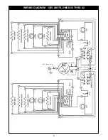
Page 7: ...3 2 12 9 6 8 1 23 14 25 26 24 22 21 23 14 15 16 17 27 18 13 BUTT SPLICE BUTT SPLICE BUTT SPLICE BUTT SPLICE WIRING DIAGRAM 120V UNITS DMXS 48 THRU 60 2 12 9 29 6 31 8 1 23 4 11 10 30 5 32 7 3 15 18 17 23 15 16 13 22 21 24 14 13 14 25 26 SPLICE SPLICE 120 VOLT 7 ...

Page 8: ... 30 THRU 42 4 11 10 5 7 3 15 13 2 12 9 6 8 1 23 14 25 26 24 22 21 14 23 15 16 13 17 20 27 19 18 15 13 19 20 23 23 16 1 8 21 14 25 26 22 24 14 15 13 3 2 12 9 6 7 5 10 11 4 BUTT SPLICE BUTT SPLICE BUTT SPLICE BUTT SPLICE BUTT SPLICE 8 ...

Page 9: ...TS DMXD 48 THRU 60 4 11 10 30 5 32 7 3 15 13 14 25 26 24 22 21 14 23 23 17 15 16 13 19 1 8 31 6 2 12 9 29 SPLICE SPLICE SPLICE SPLICE 20 18 19 15 13 23 23 28 16 21 22 24 14 25 14 26 13 15 2 12 9 29 6 31 1 8 4 11 10 30 5 32 7 3 9 ...

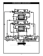
Page 10: ...HELF BLANKET HEATER FOR BOTTOM SHELF HEATERS LIGHTS FOR TOP SHELF HEATERS LIGHTS FOR MIDDLE SHELF THERMOSTAT THERMOSTAT SWITCH SWITCH PILOT LIGHT 18 PILOT LIGHT EXISTING WIRE EXISTING WIRE EXISTING WIRE EXISTING WIRE 35 REMOVE JUMPER FROM END TERMINALS SHIFT JUMPER OVER ONE SPOT L1 L2 1 1 2 3 4 5 6 6 7 8 9 10 11 11 12 12 12 13 13 13 13 13 14 14 15 15 16 16 17 17 18 19 20 21 22 23 23 24 25 26 27 28...

Page 11: ...PW Wyott Service Department directly at 214 421 7366 or 800 527 2100 fax 214 565 0976 WARNING This product has no user serviceable parts To avoid damage to the unit or injury to personnel use only Authorized APW Wyott Service Agents and genuine APW Wyott Parts when service is required WARNING Genuine APW Wyott Replacement Parts are specified to operate safely in the environments in which they are ...

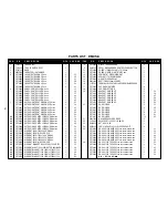
Page 12: ...2 2 1 1 1 1 1 1 30 36 42 48 54 60 30 36 42 48 54 60 30 36 42 48 54 60 30 36 42 48 54 60 30 36 42 48 54 60 30 36 42 48 54 60 8 9 10 11 12 13 14 15 16 17 18 19 20 21 22 23 24 25 21779625 8816300 21779606 21779786 21779680 21779618 54001400 1107301 21776245 21776246 21776276 21776216 21776300 21776323 21776348 21776370 21779617 21779617 21779617 21779617 21779617 21779617 54001500 1311800 8430800 863...

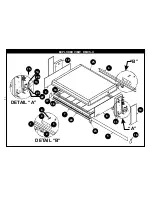
Page 13: ...EXPLODED VIEW DMXS H A B DETAIL B 1 2 9 3 4 DETAIL A 15 14 20 13 22 21 12 25 6 8 8 10 5 7 19 17 18 24 23 11 16 13 ...

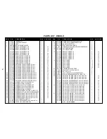
Page 14: ... ELEMENT BLANKET 120V 450W 53 750X21 750 1 1 1 1 3 3 3 3 3 3 1 1 1 1 1 1 3 3 3 3 3 3 1 1 1 1 1 1 2 2 2 2 2 2 1 1 1 1 1 1 30 36 42 48 54 60 30 36 42 48 54 60 30 36 42 48 54 60 30 36 42 48 54 60 30 36 42 48 54 60 30 36 42 48 54 60 8 9 10 11 12 13 14 15 16 17 18 19 20 21 22 23 24 25 26 21779669 8816300 21779608 21779607 21779630 21779635 21779618 54001400 1107301 21776245 21776246 21776276 21776216 2...

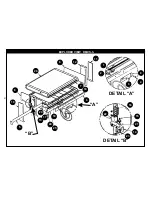
Page 15: ...EXPLODED VIEW DMXS S DETAIL B DETAIL A A B 25 26 24 23 22 21 15 14 13 12 11 17 18 19 20 16 1 2 8 8 10 5 7 6 9 4 3 15 ...

Page 16: ...2 2 2 2 2 2 4 4 4 4 4 4 2 2 2 2 2 2 4 4 4 4 4 4 1 1 1 1 1 1 4 1 11 12 13 14 15 16 17 18 19 20 21 22 23 24 25 26 27 21779785 21779685 21779618 54001400 1107301 21776245 21776246 21776276 21776216 21776300 21776323 21776348 21776370 21779617 21779617 21779617 21779617 21779617 21779617 54001500 1311800 8430800 8632000 8816600 21779811 21779813 21779815 21779817 21779819 21779821 21779828 21779829 21...

Page 17: ...EXPLODED VIEW DMXD H DETAIL B 15 14 20 13 22 21 DETAIL A 24 1 2 9 3 4 A B 27 26 12 25 17 18 23 11 16 8 8 6 6 5 7 10 10 19 17 ...

Page 18: ... DMX FLAT DECAL MECHANDIZER CONTROL PANEL BOTTOM COVER LT SINGLE SLANT LT SIDE RED COVER SINGLE SLANT RT SIDE RED 2 2 2 2 4 4 4 4 4 4 2 2 2 2 2 2 4 4 4 4 4 4 2 2 2 2 2 2 4 4 4 4 4 4 1 1 1 1 1 1 4 1 1 1 12 13 14 15 16 17 18 19 20 21 22 23 24 25 26 27 28 21779630 21779635 21779618 54001400 1107301 21776245 21776246 21776276 21776216 21776300 21776323 21776348 21776370 21779617 21779617 21779617 2177...

Page 19: ...EXPLODED VIEW DMXD S DETAIL A 25 1 2 9 4 3 DETAIL B 23 22 21 16 15 14 A B 26 24 27 8 8 19 10 5 13 17 20 6 12 11 7 28 18 19 ...

Page 20: ...2 toasters or rollergrills which have in store service The following conditions are not covered by warranty Equipment failure relating to improper installation improper utility connection or supply and problems due to ventilation Equipment that has not been properly maintained calibration of controls adjustments damage from improper cleaning and water damage to controls Equipment that has not been...

Reviews: