background image

Revised 4/23/19

Copyright © 2019 Aqua Creek Products All Rights Reserved

Revised 4/23/19


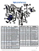
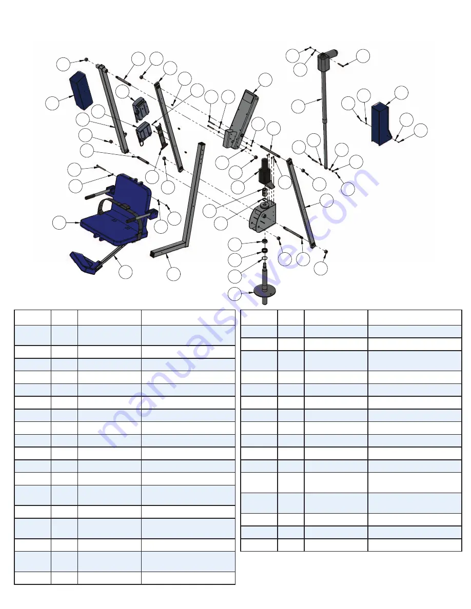
Mighty 600 Parts List

ITEM # QTY

PART #

DESCRIPTION

1

1

MTY-100WM-00

ANCHOR SPINDLE 

WELDMENT

2

1

MTY-200WM-00

MAIN FRAME WELDMENT

3

2

MTY-400-00

CONTROL ARM ASSEMBLY

4

1

AMTY-600-00

TOP CASING ASSEMBLY

5

1

MTY-700-00

CHAIR CRADLE ASSEMBLY

6

1

AMTY-800-00

LIFTING ARM ASSEMBLY

7

1

MTY-900-00

MIGHTY MOTOR ASSEMBLY

8

1

SA-0904WDCAB

22” CHAIR ASSEMBLY

9

1

F-0904FRA

FOOTREST ASSEMBLY

10

1

341185-01

ACTUATOR, LINAK, 600MM

11

1

VCB10

VITO CONTROL BOX

12

1

VCP100-29800

VITO 24V BATTERY

13

1

GT10 (CONTROL 

BRACKET)

VITO MOUNTING BRACKET

14

1

FW505520

NEEDLE ROLLER BEARING

15

1

93576A250

SPIRAL EXTERNAL 

RETAINING RING

16

1

94751A785

EXTERNAL RETAINING RING

17

1

BEARING, ROLLER 

LM67048

ROLLER BEARING & RACE

18

1

WBB263897

1” CLAMP ON SHAFT COLLAR

17

14

15

1

27

30

27

16

18

7

21

3

27

19

20

34

20

19

25

24

31

31

26

10

26

24

25

30

25

24

4

24

22

5

9

8

24

25

24

28

23

27

33

6

32

3

27

29

27

27

13

19

11

12

27

ITEM NO.

PART NUMBER

DESCRIPTION

QTY.

1

MTY-100WM-00

ANCHOR SPINDLE WELDMENT

1

2

MTY-200WM-00

MTY MAIN FRAME WELDMENT

1

3

MTY-400-00

CONTROL ARM ASSEMBLY

2

4

AMTY-600-00

MIGHTY 600 TOP CASING 

ASSEMBLY

1

5

MTY-700-00

CHAIR CRADLE ASSEMBLY

1

6

AMTY-800-00

MIGHTY 600 LIFTING ARM 

ASSEMBLY

1

7

MTY-900-00

MIGHTY MOTOR ASSEMBLY

1

8

SA-0904WDCAB

CHAIR, 22" WIDE SEAT ASSEMBLY, 

BLUE

1

9

F-0904FRA

FOOTREST ASSEMBLY, STANDARD, 

ANGLED, SPECIFY COLOR

1

10

341185-01

ACTUATOR, LINAK, 600MM, 

MIGHTY STYLE

1

11

VCB10

CONTROL BOX, VITO, 2-PORT, 

10AMP, BATTERY LEVEL INDICATOR

1

12

VCP100-29800

BATTERY, 24V BATTERY PACK, 

SEALED, LEAD ACID, VITO

1

13

GT10 (CONTROL 

BRACKET)

BRACKET, MOUNTING, VITO

1

14

FW505520

NEEDLE ROLLER BEARING

1

15

93576A250

SPIRAL EXTERNAL RETAINING RING 

(MCMASTER)

1

16

94751A785

EXTERNAL RETAINING RING 

(MCMASTER)

1

17

BEARING, ROLLER 

LM67048

ROLLER BEARING & RACE FOR 

REVOLUTION

1

18

WBB263897

1" CLAMP ON SHAFT COLLAR 

(GLOBAL)

1

19

BSH 10 X 3-8

BOLT, 316 SS, 10-24 X 3/8 SHCS

4

20

WF 10

WASHER, FLAT, #10 SAE, 316 SS

2

21

BHW 1-4 X 3-8

BOLT,  1/4-20 X 3/8 HWH, 

SERRATED, PATRIOT CASTERS

4

22

BH 5-16 X 3

BOLT, 316 SS, 5/16-18 X 3 HCS

2

23

BH 5-16 X 4 1-2

BOLT, 316 SS, 5/16-18 X 4 1/2 HCS

1

24

WF 5-16

WASHER, FLAT, 5/16, 316 SS

8

25

NN 5-16

NUT, 316 SS, NYLOCK, 5/16"-18

5

26

BS 3-8 X 2 18-8

BOLT, 18-8, 3/8 X 2 SHOULDER, 

5/16-18 THREAD

2

27

NN 3-4

NUT, 316 SS, NYLOCK, 3/4"-10

8

28

TS 3-4 X 6

THREADED STUD, 18-8, 3/4-10 UNC 

2A, BOTH ENDS PARTIALLY 

THREADED

1

29

TS 3-4 X 8

THREADED STUD, 18-8, 3/4-10 UNC 

2A, BOTH ENDS PARTIALLY 

THREADED

1

30

TS 3-4 X 10 1-2 

THREADED STUD, 18-8, 3/4-10 UNC 

2A, BOTH ENDS PARTIALLY 

THREADED

2

31

BRB FB-68-3

BUSHING, BRONZE FLANGE, 3/8 X 

1/2 X 3/8 X 3/32

2

32

14530

CLIP, ROUTING, 3/8" DIAMETER FITS 

1/4" DIAMETER

3

33

F-UBC

COVER, UNIVERSAL BATTERY 

COVER

1

34

F-MTMC

MIGHTY MOTOR COVER

1

ITEM # QTY

PART #

DESCRIPTION

19

4

BSH 10 X 3/8

#10 X 3/8 SOCKET HEAD

20

2

WF 10

#10 FLAT WASHER

21

4

BHW 1/4 X 3/8

1/4-20 X 3/8 HEX WASHER 

BOLT

22

2

BH 5/16 X 3

5/16-18 X 3 HEX BOLT

23

1

BH 5/16 X 4 1/2

5/16-18 X 4 1/2 HEX BOLT

24

8

WF 5/16

5/16 FLAT WASHER

25

5

NN 5/16

5/16-18 NYLOCK NUT

26

2

BS 3/8 X 2 18-8

3/8 X 2 SHOULDER BOLT

27

8

NN 3/4

3/4-10 NYLOCK NUT

28

1

TS 3/4 X 6

3/4-10 X 6 THREADED STUD

29

1

TS 3/4 X 8

3/4-10 X 8 THREADED STUD

30

2

TS 3/4 X 10 1/2

3/4-10 X 10 1/2 THREAD 

STUD

31

2

BRB FB-68-3

3/8 X 1/2 X 3/8 X 3/32 

BRONZE FLANGE BUSHING

32

3

14530

3/8 DIAMETER ROUTING CLIP

33

1

F-UBC

UNIVERSAL BATTERY COVER

34

1

F-MTMC

MIGHTY MOTOR COVER

13

Summary of Contents for F-MTY600

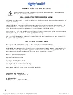
Page 1: ...damaged part is not used If any damage occurred in transit Aqua Creek Products LLC must be notified within three days of receipt of unit Proper installation cannot be overstressed as an improper installation voids Aqua Creek s warranty and may affect the safety of the user READ CAREFULLY PART F MTY600 US PATENT PENDING 16 205 638 US PATENT NUMBER D507 769 S 600 LB 272 kg MAXIMUM WEIGHT CAPACITY FO...

Page 2: ... a minimum 8 AWG 8 4mm2 solid copper conductor between this unit and the means for local equipotential bonding Check the unit periodically for signs of deterioration Keep all nuts bolts and screws tight to be sure the lift is in safe working condition SAVE THESE INSTRUCTIONS Affix supplied ADA POOL SPA LIFT sign in a location visible from the lift at all times Rechargeable batteries are to be remo...

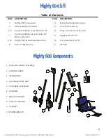
Page 3: ...ble of Contents PAGE DESCRIPTION PAGE DESCRIPTION 3 Mighty 600 Components 12 Battery Test Cable Instructions 4 ADA Installation Guidelines 13 Pinch Point Locations 5 6 Anchor Installation Core Drill Retro Fit 14 Proper Care of Pool Spa Lifts 7 Anchor Installation Saw Cut Retro Fit New Construction 15 Mighty 600 Parts List 8 10 Mighty 600 Lift Assembly Instructions 16 Seat Assembly Parts List 11 Ba...

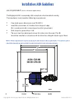
Page 4: ...imum of 24 inches from the pool edge For curved pool walls contact Aqua Creek for placement Deck slope no greater than 1 48 The seat must be submerged at least 18 inches into the water The lift should be installed at a location with 42 48 inches of depth deck to pool floor NOTE Other requirements may be necessary based on local code requirements The anchor system should be bonded according to NEC ...

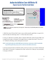
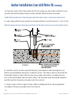
Page 5: ... bit for the fixing anchor drilling down at least 4 NOTE Create a depth marker on the drill bit with black electrical tape to make sure you drill to the right depth If you drill through the deck you may need to use the saw cut installation instructions 3 Remove plug and clean out the holes with a wire brush Insert an air nozzle to the bottom of the hole Use a pump or compressed air to blow out the...

Page 6: ...poxy gets inside the anchors 7 Let the epoxy cure for at least 24 hours before installing the lift or where applicable according to the epoxy manufacturers instructions 6 Install the anchor into the epoxy filled hole by pushing down and twisting back and forth to evenly distribute the epoxy around the anchor Push down until it is flush with the finished deck surface Clean off any excess epoxy Adjus...

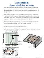
Page 7: ...nd the anchor sleeve according to your local code requirements by using the bonding lug and bonding screw on the side of the anchor sleeve 5 Pour your concrete and finish the pool deck surface 6 Once the concrete has cured your lift is ready to be mounted into the anchor sleeve 4 6 MIN 12 MIN 32 MAX 12 MIN 4 6 MIN 24 MIN 44 MAX 3 1 2 POOL WALL 2 19 O D X 6 BRONZE ANCHOR ASSEMBLY 1 O D X 4 FIXING A...

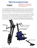
Page 8: ...stall the 1 2 x 1 1 2 hex bolt and washer to hold down the lift Tighten the bolt 2 Remove all of the shipping materials from the lift Slide the CHAIR AND CHAIR ARM ASSEMBLY up through the top casing of the MAIN ASSEMBLY and connect using the supplied 5 16 hex bolts washers and nylock nuts For standard pool configuration the CHAIR ARM will be connected at the top two holes However the chair arm can...

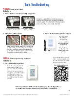
Page 9: ...Put some dielectric grease on the contact points before reattaching the battery Note If you feel your lift is malfunctioning due to a faulty battery or connections contact Aqua Creek Products for a testing kit For troubleshooting videos Visit www aquacreek com or scan the QR code below using your smartphone The Charger is ON when the green light is glowing The Battery is CHARG ING when the orange ...

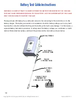
Page 10: ...onnector for connecting to the control box or to the battery charger The battery connector is not suitable to check the battery voltage as it is very hard to probe the connector without shorting out the battery which will cause damage For this reason a separate battery test cable is provided To safely check the battery voltage use a voltmeter or multi meter with standard test probes and insert the...

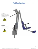
Page 11: ... 2019 Aqua Creek Products All Rights Reserved Revised 4 23 19 CAUTION PINCH POINT AREA LIFT TO BE STICKERED ON EACH ARM CAUTION PINCH POINT AREA LIFT TO BE STICKERED ON INSIDE FACE OF ARM PinchPointLocations 11 ...

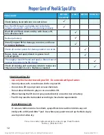
Page 12: ...ift s finish Check all warning and cautionary labels to make sure they are not faded or worn Replace as needed ProperCareofPool SpaLifts PROPER CARE NOTES Use only fresh water to wash your lift Do not wash with pool water Use only clean soft non abrasive cloths on your lift Do not store lift in pump room or near chemicals Do not allow children to play on or around this lift When cleaning the lift ...

Page 13: ...G RING 17 1 BEARING ROLLER LM67048 ROLLER BEARING RACE 18 1 WBB263897 1 CLAMP ON SHAFT COLLAR 17 14 15 1 27 30 27 16 18 7 21 3 27 19 20 34 20 19 25 24 31 31 26 10 26 24 25 30 25 24 4 24 22 5 9 8 24 25 24 28 23 27 33 6 32 3 27 29 27 27 13 19 11 12 27 ITEM QTY PART DESCRIPTION 19 4 BSH 10 X 3 8 10 X 3 8 SOCKET HEAD 20 2 WF 10 10 FLAT WASHER 21 4 BHW 1 4 X 3 8 1 4 20 X 3 8 HEX WASHER BOLT 22 2 BH 5 1...

Page 14: ...ber the dates of purchase and installation and the exact nature of the defect Within thirty 30 days after receipt of a written warranty claim by Aqua Creek and barring any unforeseen delays the place of purchase will be notified of Aqua Creek s decision regarding the claim If requested by Aqua Creek any defective product must be returned freight prepaid by customer to Aqua Creek s designated facto...

Reviews: