ENGLISH
53
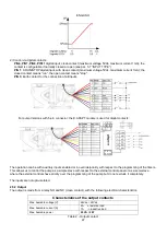
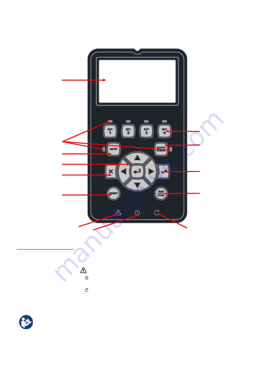
4.2 Keyboard and Display
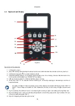
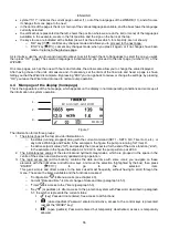
Figure 6
Description of the elements:
1. LCD graphic screen
2. (Six) LED warning light indicating the active function; each LED indicates the activation of the key next to it.
3. LED red warning light (
), for alarm indication (fault).
4. LED white warning light ( ), lit to indicate that the board is live; if it is blinking, it means that the board is live,
but the pump is not enabled (see “
RUN/STOP
” key below).
5. LED green warning light ( ), indicates that the pump is running.
6. (Four) keys “
SET 1-4
” for manual control of switching on, for directly selecting (or deselecting) a set flow or
speed (setpoint).
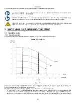
The table in chapter 7 shows the factory values of the setpoints associated with the keys from “SET1” to
“SET4”. These values are suitable for most installations, but they can be easily changed if desired (see
5.2).
7.
Key for activating “
QuickClean
” mode, to command quick cleaning or quick recirculating with a high flow rate.
8. Key for enabling “
Auto
”, mode, for activating the automatic control of the pump (which may be timed (“
Timers”
)
or given by external signals (“
EXT”
).
9.
Keys for navigating and accessing the menus:
1.
2.
6.
7.
10.
13.
5.
4.
3.
12.
11.
9.
8.

