© 2008 Aqua-Hot
®
600-D Hydronic Heating System Installation Manual
— Page 34 —
section 9: Electronic Controller Wiring
1.
Calculate the necessary wire gauge for the 12 Volt-DC
power and ground wires.
A.
Determine the total maximum amperage draw of
the Aqua-Hot heating system by adding the total
maximum Amps of the installed heat exchang-
ers (consult the heat exchanger manufacturer for
Amp-draw information) to the Aqua-Hot heater’s
22 Amps.
NOTE:
Each heating zone “FAN” circuit can supply up to
2.0 Amps of direct current. Each Aqua-Hot Cozy
heat exchanger draws .23 Amps of direct current.
For example, an Aqua-Hot heater with six Aqua-
Hot Cozy heat exchangers draws a total of 23.38
Amps ((6x.23)+22).
B.
Determine the total length of wire required to
connect the Electronic Controller to the vehicle’s
battery.
C.
Reference Appendix B with the total Amps and
length of wire to determine the necessary wire
gauge. For example, an Aqua-Hot heater with 6
Aqua-Hot Cozy heat exchangers with the Elec-
tronic Controller placed 15 feet from the vehicle’s
battery would require an 8-gauge wire.
2.
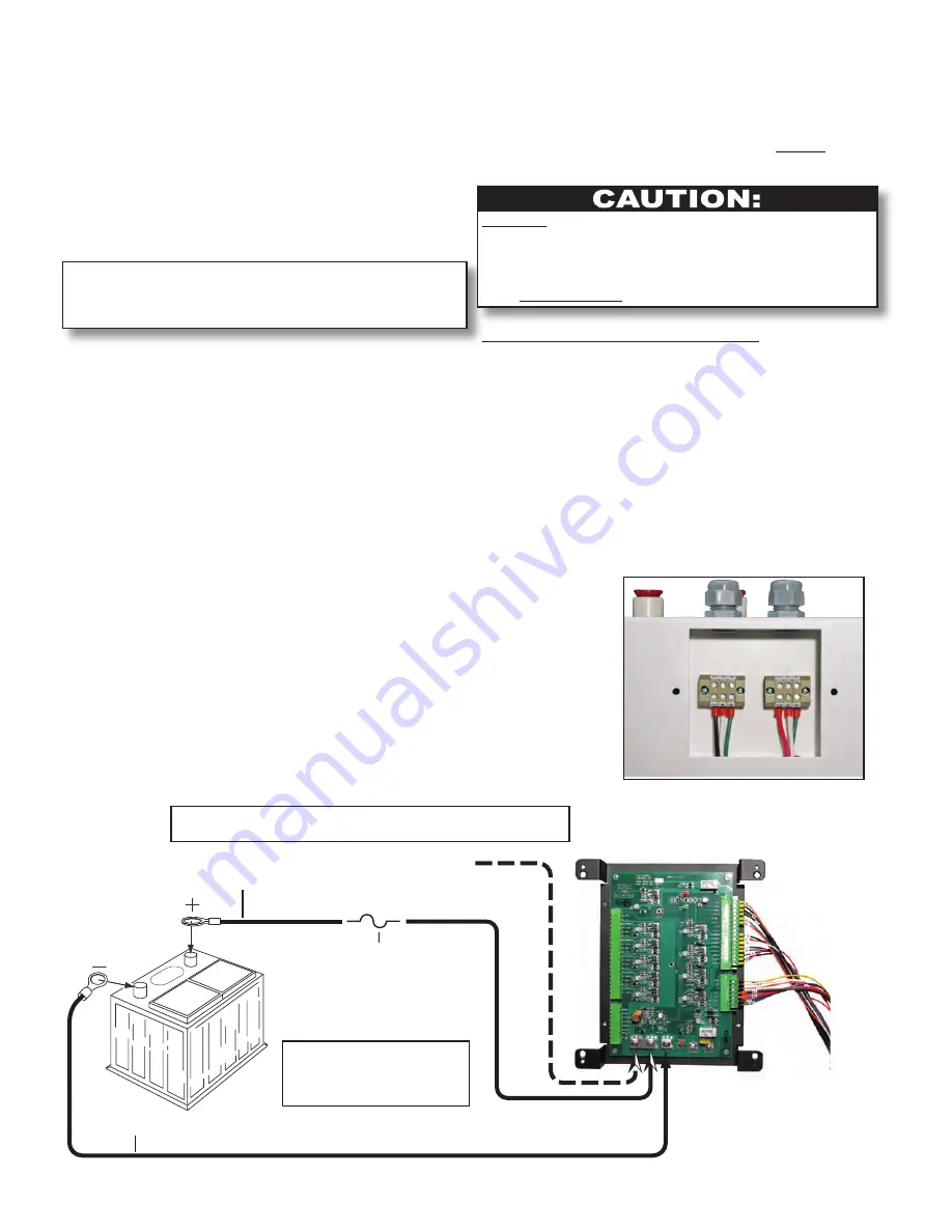
Run and connect two wires –– one red (+) wire and
one black (-) wire (power and ground), from the ve-
hicle’s battery to the Aqua-Hot’s electronic controller.
Reference Appendix A and Figure 45.
3.
Label the wires indicating whether they are a power or a
ground wire.
4.
Attach the DC power wires onto the appropriate ter-
minal/battery connections on the electronic controller.
Reference Appendix A.
5.
Connect both power and ground wires
directly
to the
vehicle’s batteries.
DO NOT
activate the diesel-burner until the antifreeze and
water heating solution has been added to the boiler tank and the
heating system has been completely bled of air. Operating the
Aqua-Hot without the antifreeze and water heating solution will
cause
serious damage
to the Aqua-Hot’s boiler tank.
Connecting the 120 Volt-AC Power:
1.
Route and insert three 120 VAC power source wires
into the terminal block access area through the ap-
propriate port’s cable clamp fitting and into the proper
terminal. Reference Appendix A and Figure 44.
2.
Secure the wires into their terminals by tightening the
corresponding screw on the terminal block.
3.
Re-install the terminal block access cover and tighten
the screws securing the cover to the Aqua-Hot.
Optional connection to the
house battery disconnect
In-line
Fuse
Positive/Power
Negative/Ground
NOTE:
Reference Appendix A
for specific electronic
controller wiring
details.
NOTE:
If the optional power connection is used, remove the jumper
plate from the two power terminals - “JP5” and “JP8.”
Figure 44
Figure 45
Summary of Contents for 600-D
Page 1: ...2008 Aqua Hot Heating Systems Inc Installation Manual...
Page 43: ...Appendix B Appendix B Wire Gauge Information...
Page 45: ...Appendix C Appendix C Electronic Controller Features...
Page 48: ...Appendix D Appendix D Antifreeze Types...
Page 50: ...Appendix E Appendix E Antifreeze Mixture Water Quality Recommendations...
Page 52: ...Appendix F Appendix F Antifreeze Terms and Mixture Ratio...


