background image

11

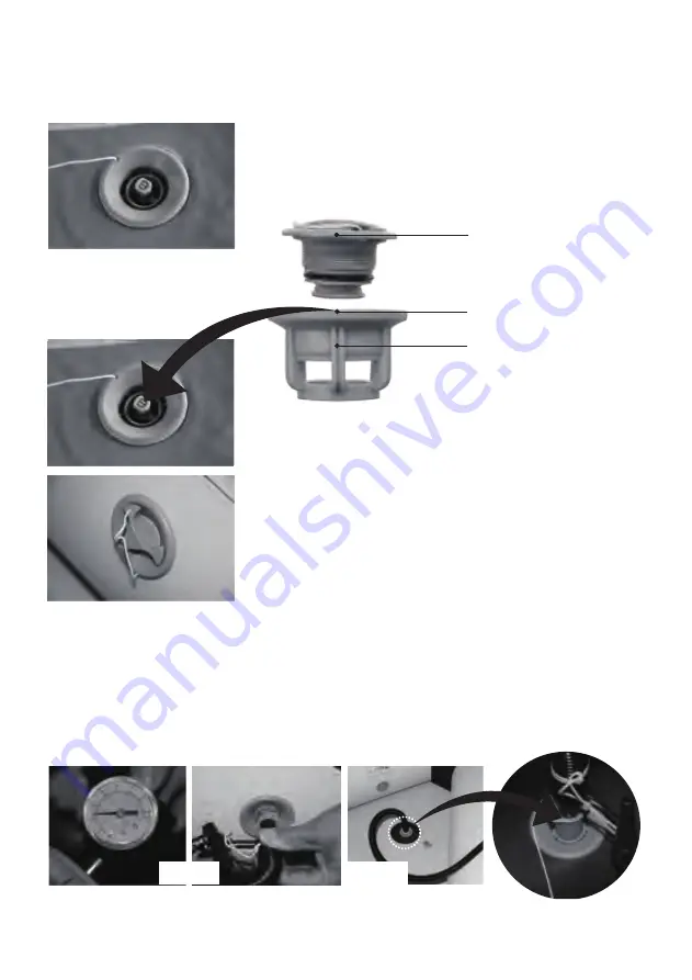
VALVE OPERATION

Follow the instructions below for valve operation and correct inflation and deflation procedures.

(This kind of valve is used for the boat hull, keel and air deck floor for BT-88850AD)

                                                          To close off the valve for inflation, make sure that the center    

                                                          valve pin is in the “UP” position. If it is in the “down” position, 

                                                           press down on the valve pin and turn it counterclockwise 

                                                           until it pops up.

VALVE DIAGRAM

                                                           To open the valve for deflation, press down on the valve pin

                                                           and turn it clockwise so it locks down.

                                                           Be careful of any sand or debris around the valve area

                                                           when deflating as small particles could become airborne

                                                           with the release of the air pressure.

                                                           Always lock the valve cover over the valve stem when in

                                                           use. This will prevent accidental air release and entrance of

                                                           any particles into the air chambers.

INFLATION STEPS

1. Ensure the air valve’s center pin is properly in position by rotating the control stem until it pops  

    out. This ensures no air escapes during inflation. 

2. Inflate the hull. After inflation, insert the provided pressure gauge into the air valve to check 

    the air pressure. The ideal pressure is 0.16bar - 0.25bar. (Fig. 1)

3. Inflate the keel (BT-88810, BT-88830 excluded)

    Stop inflating until the pressure reaches 0.3bar. (Fig. 2)

Valve cap

Button

Valve base

Fig.2

Fig.1

Summary of Contents for BT-06300AL

Page 1: ...LATABLE SPORT BOATS User s Guide Model BT 88810 BT 88830 BT 88850 BT 88850AD BT 88850AL BT 06300WD BT 06300AL BT 06330WD BT 06330AL BT 06360WD BT 06360AL 2016 2017 Version w w w a q u a m a r i n a c...

Page 2: ...safe use and pleasure from your Aqua Marina boats GENERAL INFORMATION SAFETY In a manual of this type it is impossible to give adequate space to the topic of water safety Check in your local area for...

Page 3: ...at for a full 24 hours before undertaking long trips DO NOT allow children to use Aqua Marina unsupervised DO NOT consume alcohol while boating or operating a boat while under the influence of alcohol...

Page 4: ...C C C C 1pc 1pc 19 hand pump 16 hand pump 1pc repair patch and glue 30ml 1pc 1pair 9 1 4 11 2 77 1 50m 9 9 5 2 96 1 53m 9 9 5 2 96 1 53m 11 5 3 30 1 53m 11 5 3 30 1 53m 12 5 9 3 59 1 76m 12 5 9 3 59 1...

Page 5: ...pairs for BT 88850 BT 88850AD AL BT 06300WD AL BT 06330WD AL BT 06360WD AL Oar holder Velcro for oar only BT 06360AL WD D ring towing rope Inflatable keel except BT 88810 30 PVC lift handle 1 pair fo...

Page 6: ...as necessary in order to slide the Board 1 into place Fig 3 1 2 Insert the Board 3 into the stern and push the board under the transom Fig 2 1 3 Align the slot on the Board 1 with the protrusion of B...

Page 7: ...fying numbers on the floorboards must be faced upwards After the assembly carefully check the floorboards are secured and tight If the floorboards are not tight or smooth re do the assembly Fig 1 Fig...

Page 8: ...it the back board to the rear end Fig 3 c Step on raised part of two connected floor sections and push down the two boards at the joint Make sure the deck is flatten by spreading inside the boat Fig 4...

Page 9: ...som FIG 2 1 3 Connect the Board 1 with Board 2 by inserting the I shape stringer FIG 3 1 4 Connect the Board 3 with Board 4 by inserting the I shape stringer FIG 4 1 5 Connect the Board 2 with Board 3...

Page 10: ...part of two connected floor sections and make sure that floor will flatten by spreading inside the boat Fig 4 Fig 5 e Connect the side stringers Fig 5 Fig 6 f Inflate left and right tube of the boat f...

Page 11: ...bris around the valve area when deflating as small particles could become airborne with the release of the air pressure Always lock the valve cover over the valve stem when in use This will prevent ac...

Page 12: ...hot weather the air will expand You must let some air out to prevent the product from failing due to overpressure Only use Aqua Marina approved inflation pumps Never use motor driven high pressure air...

Page 13: ...tor power marked on the boat label OPTIONAL CONSOLE INSTALLATION Refer to AM removable fiberglass steering console instruction NOTE The console should be installed before the inflation of keel OAR ASS...

Page 14: ...ing agents as possible do not discharge waste agents into water and clean your boat preferably on land Be sure your product is completely dry before storing The products may be stored inflated but do...

Page 15: ...ng included vinyl repair patch and vinyl glue You can also purchase additional PVC or silicon based glue for repairing camping mats tents or shoes from your local market to patch your boat Please refe...

Page 16: ...costs losses or damages incurred as a result of loss or use of this product 5 This warranty does not cover damage caused by misuse abuse neglect normal wear and tear including but not limited to punct...

Reviews: