background image

27

Deutsch

English

Français

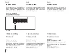
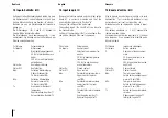
12 Time-Schleife: 3

DAT:

Datum

TIM:

Zeit

Hr:

Betriebsstunden

Err:

Fehlerstunden

SEA:

Sommer- oder Winterzeit

St1:

Stichtag 1

St2:

Stichtag 2

Im CALEC

®

ST können 2 Stichtage programmiert

werden, in dem bei der Anzeige St1 bzw. St2 der
Service-Mode aktiviert, und die Enter Taste betätigt
wird.

12 Time Loop: 3

DAT:

Date

TIM:

Time

Hr:

Operating hours

Err:

Hours of error

SEA:

Summer or Winter time

St1:

Billing date 1

St2:

Billing date 2

Two billing dates can be programmed into the
CALEC

®

ST whereby the Service Mode is activated

when either St1 or St2 is shown in the display and
the Enter key is pressed.

12 Boucle Time : 3

DAT:

Date

TIM:

Heure 

Hr:

Heures de fonctionnement

Err:

Heures d’erreur

SEA:

Heure d’été ou d’hiver

St1:

Jour de relevé 1

St2:

Jour de relevé 2

Sur le CALEC

®

ST, 2 jours de relevé peuvent être pro-

grammés en affichant St1 et St2 du mode Service, et
en actionnant la touche Enter.

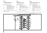
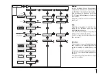
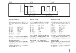
DAT        01.06.03

TIM               08:15

tIME

Hr               1234 h

Err                   0 h

SEA           WintEr

St1              30.06.--

St2              31.12.--

3

Season:
- Summer
- Winter

Stichtag 1

Stichtag 2

Time HH:MM

Error hours

Operating hours

13

Edit

Edit

Edit

Edit

Edit

Summary of Contents for CALEC ST

Page 1: ...CALEC ST CALEC ST FLOW Montage und Bedienungsanleitung Mounting and operating instructions Instructions de montage et mode d emploi 5 98 RH 130 40 F 55 C 5 VD 3 188 def 07 2012 ...

Page 2: ...with electrical circuits with dangerous voltages 24 V AC or 42 V DC may only be carried out by authorised experts with due regard to local regulati ons The mains supply may only be connected to termi nals L and N Any other terminal connections may be life threatening The instrument may be destroyed The mains supply must be the same circuit that sup plies the heating or cooling installation or else...

Page 3: ...ions 18 7 1 Reading instructions 18 7 2 Display 19 7 3 Operating modes 20 8 Flow chart 21 8 1 Caption 21 9 Main loop 0 23 10 Information loop 1 25 11 Actual loop 2 26 12 Time loop 3 27 13 Billing date loop 4 28 14 Logger loop 5 29 15 Input loop 6 30 16 Output loop 7 32 16 1 Pulse function 34 16 1 1 CALEC ST Standard 34 16 1 2 CALEC ST BDE option 34 16 1 3 CALEC ST TGR 34 16 1 4 CALEC ST Flow 34 16...

Page 4: ...oop 12 46 22 Date entry 13 46 23 Commissioning 47 23 1 CALEC ST Standard 47 23 1 1 Introduction 47 23 1 2 Preparation 47 23 1 3 Programming 48 23 1 4 Function control 49 23 2 Instrument versions and options 49 23 2 1 BDE option 49 23 2 2 GLY option 50 23 2 3 Mass option 50 23 2 4 LON board 50 23 2 5 CALEC ST Flow 50 24 Data back up 51 25 Recalibration auditing 51 25 1 Expiry date 51 25 2 Audit mod...

Page 5: ...eter sensor of a measuring point are adjusted to be compatible with one another and should not be replaced If temperature sensors are connected in four wire technology the cable length must not exceed 15 meter In case of connection in two wire technology the max cable length is acc to EN 1434 2 chapter 3 3 4 Reference value for common temperature sensors Pt 100 2 5 m Pt 500 12 5 m Verified instrum...

Page 6: ...aterial Matériel livré outils et matériel de montage Scope of supply tools and mounting material CALEC ST Æ 3 x Ø4 3 x Ø6 Torx TX 15 Ø6 3 x 4 3 x 12 3 5 x 0 6 1 5 x 2 Gehäuse öffnen Ouvrir le boîtier Open casing 1 2 1 Option 2 230 V AC ...

Page 7: ...7 3a Montage auf DIN Schiene Mounting on DIN rail Montage sur rail porteur DIN 3b Montage auf ebener Wand Mounting on flat wall Montage mural sur paroi plat 1 2 3 Click 1 2 ...

Page 8: ...e Innenseite Deckel Wiring diagram see inside cover Diagr de connection voir à l intérieur du couvercle 5 Signalleitungen und ggf Kleinspannungsversorgung anschliessen Connect signal cables Connecter les câbles signaux 1 2 3 ...

Page 9: ...min 6 mm 3 6 Wenn zutreffend Netzspannung anschliessen und Stützbatterie einsetzen Art Nr 92402 92403 92465 Connect mains and insert the internal battery Part No 92402 92403 92465 Connectez secteur et insérez la pile de support n d article 92402 92403 92465 Click 2 1 5 3 4 ...

Page 10: ...10 7 Gehäuse schliessen Close casing Fermer boîtier 1 2 3 3 2 ...

Page 11: ... 0 Cover 1 Liquid Crystal Display LCD 2 Enter key 3 Select key 4 Sight glass if verified with calibration mark 5 Optical M Bus interface 6 Service key 8 Nameplate of totaliser module 9 Cover screws 5 Vue de l appareil 0 Couvercle 1 Affichage à cristaux liquides ACL 2 Touche Enter 3 Touche de sélection 4 Fenêtre d inspection si étalonné avec marque d étalonnage 5 Interface M Bus optique 6 Touche Se...

Page 12: ...3 Plug in totaliser module 14 Connector module 15 Cable duct M12 with plastic seal 16 Cable port M16 mains version 17 Options module 18 Cable duct M16 with plastic seal 10 Ouvertures de montage 11 Support mural pour rails de montage 12 Charnière du couvercle 13 Module du calculateur enfichable 14 Module de bornes 15 Passe câble M12 fermé par une membrane en elastomer 16 Presse étoupe M16 version s...

Page 13: ...1 Terminal assignments The diagram shows an example of typical modules and their terminal assignments A Terminal module terminal block a B Plug in totaliser module C Optional module 1 terminal block c D Optional module 2 terminal block d 6 Connexions électriques 6 2 Disposition des bornes Le graphique représente les modules possibles et la disposition des bornes A Module de bornes bornier a B Modu...

Page 14: ...c device without optional modules Appareil de base sans modules optionnels 92400 92401 Mit M Bus Karte With M Bus board Avec carte M bus 92435 Mit Ausgangskarte With output board Avec cartes de sortie 92434 Mit M Bus Karte 2 für Batteriegerät With M Bus board 2 for battery device Avec carte M bus 2 pour appareil à pile 92436 ...

Page 15: ... LON Karte mit Kleinspannungsversorgung With LON board with low voltage supply Avec carte LON avec alimentation basse tension 92500 Mit LON Karte 230 V AC With LON board 230 V AC Avec carte LON 230 V CA 92481 ...

Page 16: ...e avec les tension externes suivantes 230 V CA aux bornes L N ou V CA ou 12 24 V CC aux bornes 60 61 Basisgerät mit Netzkarte Basic device with mains board Appareil de base avec carte réseau 92402 92403 93117 Basisgerät mit Netz und M Bus Karte Basic device with mains and M Bus board Appareil de base avec carte réseau et M Bus 92499 Klemmenanordnung der Analogausgangskarte siehe separates Dokument...

Page 17: ... carte réseau et LON 92481 Basisgerät mit Netz und LON Karte 24 V AC Basic device with mains and LON board Appareil de base avec carte réseau et LON 92500 M Bus Karte 2 für Netzgerät mit Kabelführung M bus board 2 for battery device with cabling Carte M bus 2 pour bloc d alimentation avec passe câble 92501 ...

Page 18: ...du compteur d énergie 7 Mode d emploi 7 1 Instructions de lecture Présentation Illustration de l appareil et de l affichage Diagrammes de séquence Description des processus de commande avec men tion des séquences partielles dans le diagramme de séquence Référence avec n et mot clé Exemple 6 INPUTS Nr1 ImP 6 4 CALEC ST Flow Beim Durchflussrechner sind am Klemmenblock a siehe Bild in Kap 6 1 keine T...

Page 19: ... Nachkommastellen werden durch einen Rahmen gekennzeichnet 4 Einheit 3 Zeichen 5 Gerät im User Mode 6 Gerät im Service Mode 7 Editier Mode Angezeigter Wert kann verändert werden 8 Alarm 9 Ohne Funktion 10 Durchflussanzeige blinkt wenn Durchfluss erkannt wird 11 Symbol für Speicherwerte Stichtag oder Logger 12 Auswahl Taste 13 Enter Taste 7 2 Display 1 Tag 3 characters 2 Numerical display with 8 la...

Page 20: ...the housing is closed freely accessible data can be shown in the display using the keys Service Mode This can be activated by pressing the service key when the cover is open It also enab les all necessary but non verifiable start up parame ters to be set and displayed Programming Mode This enables the complete range of settings including calibrated values to be made This can be activated only if t...

Page 21: ...ss Programming key under seal Display This can have other units Display under certain conditions Unit in User Mode Unit in Service Mode Unit in Edit Mode Display of logger data and billing rea dings 8 Diagramme de séquence 8 1 Légende Activer la touche de sélection Activer la touche Enter Activer simultanément la touche de sélection et Enter Activer la touche Service Activer la touche Programme so...

Page 22: ...data Right Normal procedure for CALEC ST standard version Left Alternative procedure for given version CALEC ST BDE Right Display field for CALEC ST standard version Left Display field for given version CALEC ST FLOW in example display not available Représentation schématique de Edit en mode Service Activer la touche Service Activer la touche Enter Saisie selon le type de données Représentation sc...

Page 23: ...nttest Momentanwerte Zeit Parameter Stichtage Loggerdaten Parameter für Inputsignale Parameter für Outputsignale Einheiten M Bus Parameter Konfigurations Parameters Produktionsparameter Energy Volume Tariff threshold return temperature Auxiliary meters Pulse parameter Installation side Error messages Display test Instantaneous values Time parameters Billing date Logger data Input signal parameters...

Page 24: ...24 ...

Page 25: ... on cold side Syst Err Error in totaliser th ALArM Temperature on hot side outside measuring range tc ALArM Temperature on cold side outside measuring range dt ALArM Temperature difference outside measuring range 10 Boucle d info 1 La boucle d info permet d afficher des erreurs ou des alarmes Elles ne s affichent que si les conditions de déclenchement ne sont pas réunies th Error Erreur sonde côté...

Page 26: ...e flow KF C Factor DEN Density of product 11 Boucle instantanée 2 Valeurs instantanées Th Température côté chaud Tc Température côté froid ΔT Différence de température P Puissance Q Débit volumique KF Facteur K DEN Densité du fluide 26 Deutsch English Français Th 40 8 C Tc 30 2 C inStAnt DT 10 58 K P 3 215 kW Q 0 263 m3 h KF 1 156 DEN 0 991 KG L 2 Density K Factor Temp hot Temp cold Power Temp dif...

Page 27: ... Two billing dates can be programmed into the CALEC ST whereby the Service Mode is activated when either St1 or St2 is shown in the display and the Enter key is pressed 12 Boucle Time 3 DAT Date TIM Heure Hr Heures de fonctionnement Err Heures d erreur SEA Heure d été ou d hiver St1 Jour de relevé 1 St2 Jour de relevé 2 Sur le CALEC ST 2 jours de relevé peuvent être pro grammés en affichant St1 et...

Page 28: ...oop 3 13 Boucle de jour de relevé 4 Sélection du jour de relevé n 1 ou 2 DAT Date du jour de relevé E Index d énergie le jour du relevé V Index volumique le jour du relevé H2 Index compteur auxiliaire 2 le jour du relevé H3 Index compteur auxiliaire 3 le jour du relevé Err Heures d erreur jusqu au jour du relevé Remarque Les jours de relevé peuvent être réglés dans la boucle Time 3 Memory Nr 1 Mem...

Page 29: ...ire les va leurs de la boucle de données et de régler l intervalle de sauvegarde dans l affichage PER en mode Service CALEC ST Masse Memory Nr 1 Memory Nr 2 LOGGEr Memory Nr 60 Memory PER Month Memory DAT 01 09 03 Memory E 12345678 KWH Memory V 12345678 m3 5 Memory H2 12345678 MWh Memory H3 12345678 MWh Memory P 0 032 KW Memory Err 0 h CALEC ST BDE V E V E CALEC ST FLOW H1 CALEC ST FLOW Month 2 dA...

Page 30: ...an only be changed if the seal is damaged Fct Volume Volume pulse Fct Impuls Auxiliary input F Selecting the maximum fre quency 20 Hz for bouncing passive transmitters 200 Hz for non bouncing active transmitters Status On Closed contact Status Off Open contact Max Permissible maximum temp Upper limit for th alarm see 1 Min Permissible minimum temp Lower limit for th alarm see 1 Tr Threshold for re...

Page 31: ...progammiert werden Nach Bestätigung der Eingabe an der Position Do it können die Einstellungen nicht mehr ver ändert werden Bitte prüfen Sie vorher genau ob alle Eingaben korrekt sind Note Depending on the model it is possible to pro gramm in the INIT Mode pulse value and installation place once only After conforming the settings at the position Do it they can t be changed any longer Due to this p...

Page 32: ...LS Pulse output Fct LiMit 1 Single limit overstep Fct LiMit 2 Double limit overstep Band Fct ALArM Alarm output Fct M bUS Output controlled by M Bus The action of the contact can be defined for all functions Act on Action active on Act off Action active off The position of the contact is also shown in the sta tus window STA on Contact closed STA off Contact open Settings of the analogue outputs no...

Page 33: ...ption Massfl ow MAS FLO t hot t cold t diff POUEr FLOU C FActor dEnSitY FLOU Hyste rese 0 10 Counter Sek Type of Output EnErGY VoLuME H2 H3 EnPos VOLPos EnNeg VOLNeg H2 H3 Type of Output H1 H2 H3 Counter Pulse Action active On active Off Status is On is Off Nr 1 Nr 2 OutPuts 7 Output N o Fct InactivE Fct IMPULS Fct LiMit 1 Fct LiMit 2 Fct ALArM Fct M bUS Edit Edit Edit Edit Edit Edit Edit Edit Edi...
Page 34: ...ergie und Volumenwert für Heizen oder Kühlen ausgegeben werden Med E Energiepuls Heizen Med E Energiepuls Kühlen Med V Volumenpuls Heizen Med V Volumenpuls Kühlen Die anderen Werte entsprechen der Standardaus führung 16 1 3 CALEC ST Option TGR Bei der Option TGR Grenzwert Rücklauf können die Register T1 und T2 über die Impulsausgänge ausge geben werden 16 1 4 CALEC ST Flow Beim Durchflussrechner w...

Page 35: ...p Kaltseite Med t dif Temp differenz Med POUEr Leistung Med FLOU Durchfluss Med C FActor K Faktor Med dEnsiTY Dichte Bei CALEC ST Flow kann nur der Momentanwert am Impulseingang 1 überwacht werden d h Durch fluss bei Volumenpuls Leistung bei Energiepuls oder Massenstrom bei Massepuls Bei einheitenlosen Pulsen HCA wird kein Moment anwert berechnet so dass die Limit Funktion nicht verwendet werden k...

Page 36: ...hrt werden 16 3 Funktion Limit 1 Die einseitige Grenzwertüberwachung Fct LiMit 1 gibt ein Ausgangssignal ab sobald das Signal einen positiven Grenzwert überschreitet bzw einen nega tiven Grenzwert unterschreitet siehe Grafik Um die inverse Funktion zu bilden kann der Wirksinn des Ausgangssignals umgekehrt werden The cumulative time in s is shown in the display Cnt for the time the limit value is o...

Page 37: ...n positiven Grenzwert GW2 unterschreitet bzw einen negativen Grenz wert unterschreitet siehe Grafik Und sobald das Signal den unteren negativen Grenzwert GW1 unterschreitet oder das Signal den oberen negativen Grenzwert GW2 unterschreitet bzw einen negativen Grenzwert überschreitet siehe Grafik 16 4 Function Limit 2 Double limit overstep monitoring Fct LiMit 2 produ ces an output signal as soon as...

Page 38: ...bUS kann der Ausgang über den M Bus gesteuert werden Cnt __s Zeigt die kumulierte Dauer während der der Kontakt geschlossen war 17 Units Schleife 8 17 1 CALEC ST Standard In der Einheiten Schleife werden folgende Grössen angezeigt bzw eingestellt 1 Die Einheiten und Anzahl Kommastellen der Anzeige für Energie Volumen Hilfszähler Leistung Durchfluss und Temperatur Die verfügbaren Werte sind in der ...

Page 39: ...0 01 0 1 1 GJ 0 001 0 01 0 1 1 m3 0 1 1 GAL USGal 0 001 0 01 0 1 1 t 0 001 0 01 0 1 1 KBT KBtu 0 001 0 01 0 1 1 MBT MBtu CALEC ST Edit Edit Edit Edit Edit Edit Prog Edit Prog Edit Edit Prog M 0 01 t 0 001 0 01 0 1 1 t CALEC ST Masse KB h KBtu h MBT MBtu h Edit Prog UnitS H2 0 001 m3 H3 0 001 m3 Q m3 h EP Pro PULS KWh 8 EP Energy pulse kWh MJ KBT KBTU VP Volume pulse L GAL USGal m3 mL m3 h GA h USG...
Page 40: ... presettings apply to all pulse inputs They limit the option for setting the pulse weighting see Input loop Section 15 18 M Bus loop 9 The following variables are shown or set in the M Bus loop ADR Primary M Bus address No 1 bAUD 1st baudrate for M Bus No 2 bAUD 2nd baudrate for M Bus Ac1 Ac2 Counts the number of calls with the appropriate baudrate 2 Un préréglage pour les impulsions d énergie et ...

Page 41: ... No 2 Access Counter M Bus No 1 Access Counter M Bus No 2 TYP M buS APP CANCEL Application reset Adr 1 247 BAU 300 38400 PAR nonE TYP ModbuS Adresse Baudrate Parity Bit nonE EVEN odd Adr 1 255 TYP n2 buS Adresse Edit Edit Edit Edit Edit Edit Edit Edit Adr Mod DIN BAcnET Adresse MAStEr SLAVE Master 0 127 Slave 0 254 Edit Edit Edit ...
Page 42: ...tre deux impulsions dépasse cette durée la valeur instanta née 0 s affiche Ftr Numéro de filtre 0 20 Filtre pour le calcul de la valeur instanta née Plus le chiffre est élevé plus la durée de temporisation Tv est importante pour le calcul de la valeur moyenne Des valeurs Tv plus élevées doivent être choisies lorsque les impulsions d entrée sont réparties irrégu lièrement sur l axe temporel sinon l...

Page 43: ...i der Inbetriebnahme sind der Wärmeträger Med und dessen Konzentration Con in einzustellen Med Wärmeträger Medium Con Konzentration des Wärme trägers Die verfügbaren Medien sind in der Grafik darge stellt Hinweis Geräte mit der Option Glykol sind nicht bau artzugelassen und können nicht geeicht werden 19 3 CALEC ST Flow Der Durchflussrechner entspricht dem Standard gerät bis auf die nicht verfügba...

Page 44: ...44 ...

Page 45: ...rd St bdE with BDE option ST FLOW Flowmeter ST M Mass flowmeter Dat Date of manufacture FW Firmware version HW Hardware version 20 Boucle système 11 Les valeurs suivantes peuvent être affichés dans la boucle système FNr N de fabrication de l appareil SYS Version du logiciel CALEC St Standard St bdE Avec l option BDE ST FLOW Débitmètre ST M Calculateur massique Dat Date de fabrication FW Version du...

Page 46: ...er with the Select key 22 Date entry 13 If a date is to be entered into an operating loop the procedure is carried out as shown in the diagram 1 Activate the Service Mode by pressing the Service key 2 Select the year month and day display Y m d with the Enter key 3 Set the number with the Select key 21 Saisie de chiffres 12 Si un nombre à plusieurs chiffres peut être introduit dans une boucle de c...

Page 47: ... other service parameters can only be changed in the field if the instrument is not a verified unit Documentation available on request 23 1 2 Preparation 1 Check the type of sensor Pt100 Pt500 and pulse value of the flow transmitter 2 Check electrical connections 3 Carry out the following settings or controls on the instrument 23 Mise en service 23 1 CALEC ST Standard 23 1 1 Introduction Cette des...

Page 48: ... e g Cold side Û Sid cold The following settings can be carried out in the Service Mode 3 TIME Dat TIM Checking setting date and time 3 TIME St1 St2 Setting the billing date For M Bus instruments 9 M Bus Adr No1bAud No2bAud Setting the primary address and baudrates When using auxiliary inputs 6 INPUTS No2 No3 ImP Selecting the pulse weighting of the auxiliary inputs H2 and H3 When using pulse outp...

Page 49: ...r start up and other displays for special instru ment versions and options 23 2 1 BDE option BDE If heating and cooling are being operated in a two pipe system the forward flow may be warmer than the return flow Using the option for bi directio nal energy measurement the CALEC ST can record the energy amounts for heating and cooling with two separate counters Energy and volume values are shown in ...

Page 50: ...given out at the pulse outputs instead of the volume This is shown as follows 0 M for mass 23 2 4 LON board CALEC ST can equipped with a LONMARK 3 2 certi fied LON interface for wired transmission with free topology FTT 10A The LON board is explained in the technical docu mentation CALEC ST LON FTT 10A interface 23 2 5 CALEC ST Flow CALEC ST Flow is a variant unit for use as a flowmeter but is not...

Page 51: ...nit with the correct calibration veri fication parameters pulse value mounting side etc has just to be plugged in Other parameters do not have to be re entered The field wiring remains connected 25 1 Expiry date Calibrated instruments are to be returned to the fac tory for recalibration once the expiry date has pas sed CALEC ST has the advantage that only the totaliser module has to be returned Th...

Page 52: ...urning this module for recalibration usually takes about 5 10 days This is speeded up for audit modules which have the following numbers Battery Pt100 92404 Battery Pt500 92405 Battery Flow 92995 Mains Pt100 92406 Mains Pt500 92407 Mains Flow 92995 25 2 Modules de révision Le réétalonnage et le renvoi de l usine du même module nécessitent de 5 à 10 jours Cela peut aller plus vite en utilisant des ...

Page 53: ... pour compteur de chaleur combiné avec un débitmètre appro prié Affichage Unités d affichage d énergie Unités d affichage de puissance Unités d affichage de volume Unités de débit volumique Unités de mass Unités de débit massique 89 336 EWG 92 31 EWG 93 68 EWG EN 1434 EN 55081 1 EN 50082 2 EN 61010 BxHxT 120 x 163 x 49 mm 5 55 C EN 1434 class C 0 60 C IEC 870 5 M Bus 2 180 C 3 177 K Pt 100 Pt 500 ...

Page 54: ...ur Tension d alimentation Cycle de calcul Plle de secours pile bouton Entrée d impulsions n 1 Fréquence max pour émetteur actif antirebond filtre inactif Fréquence max pour émetteur passif rebond filtre actif Durée d impulsion min Durée de pause min Entrée d impulsions n 1 NAMUR Seuil de déconnexion Seuil de connexion 60 1 M 2 d 1 d 1 M 2 d 1 d 1 h EEPROM 10 a DT DTmin 0 2 99 K Limit 1 Limit2 3 V ...

Page 55: ...55 Deutsch English Français 27 Bohrschablone 27 Hole template 27 Gabarit de perçage ...

Page 56: ... SPRL Ringstrasse 75 Rue du Jura 10 Kurt Schumacher Allee 2 Dallaan 67 CH 4106 Therwil CH 1800 Vevey D 28329 Bremen B 1933 Sterrebeek Tel 41 61 725 11 22 Tel 41 21 926 77 77 Tel 49 421 871 64 0 Tel 32 2 241 62 01 Fax 41 61 725 15 95 Fax 41 21 926 77 78 Fax 49 421 871 64 19 Fax 32 2 216 22 63 info aquametro com info vevey aquametro com info amd aquametro com info amb aquametro com www aquametro com...

Reviews: