User Manual Thermal X - R Series Chillers
Page 24
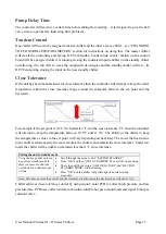
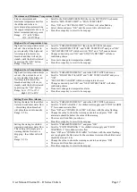
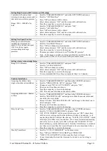
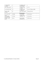
Controller Input and Output Schematic
Connector
Type
Control
Outputs – OUT1 to OUT12
across the top of the board
24VDC
0-10 Volt out put
0-10 Volt out put
1 Compressors
2 Hot Gas/ Spray Cool
3 Pump
4 Ball Valve
5 Fan Bank
6 Master Fault
7 Master Run
8 Standby/ Tandem link enable/ Status
11 Variable Speed Compressor Control
12 Fan speed control
Inputs – IN1 to IN10 across
the bottom of the board
IN1 (NOT USED)
IN1
IN2
IN3
IN4
IN5
IN6
IN7
IN8
IN9
IN10
Not Used
0-10V Input
0-10V NC Input
0-10V NC Input
0-10V/ NTC thermistor
0-10V/ NTC thermistor
0-10V/ NTC thermistor
0-10V/ NTC thermistor
0-10V NC input
0-10V Input
0-10V input
Not Used
Supply Pump Flow Meter
Compressor 1 fault input
ON/OFF Switch
Plate pack safety sensor
Ambient temperature sensor
Chilled water supply temperature sensor
Chilled water return temperature sensor
Standby/ Tandem link
Suction pressure
Discharge pressure
Please note: There are two IN1s at the bottom of the board. The first IN1 at the edge is not used.

