background image

Residential Steambath Generator Systems

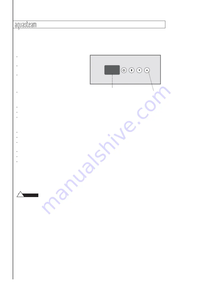
Operation of the In-Shower Control

On/Off Key

ON/OFF K ey is used to turn the steam generator

on/off.

Press On/Offkey to turn steam generator on.

Press a second time to turn steam generator off.

A built-in timer automatically shuts the steam

generator offa predetermined period of time
after it has been started, unless the user does so
manually.

The "Display" indicates the S et Point temperature.

Pause Key

Pause key is used to turn the steam generator offmomentarily.

Press Pause key to activate stand-by mode. Press a second time to resume normal function.

The "S et Point" indicator will flash on the function panel when Pause feature is activated.

Scroll Up & Scroll Down Keys

Up & Down arrow keys are used to set ambient temperature.

Pressing and holding keys will increase or decrease the current temperature setting.

The new and desired temperature setting ("S et Point" value) will remain for 5 seconds on the LE D display as

a confirmation of the new value you have selected.

The "S et Point" indicator shows the desired temperature, NOT the actual temperature.

Temperature can be adjusted in 1˚ F (0.5˚ C) increments from 105-120˚F (40.0- 49.0°C).

When ambient temperature is 1˚ F (0.5˚ C) lower than the S et Point, the heater automatically comes on

until the temperature reaches S et Point plus 1˚ F (0.5˚ C).

Care Tips for Controls

1. Use only mild soap and water on a soft cloth to clean the control.

2. Do not use abrasive cleansers

Do not route the control or temperature sensor wiring inside conduit together with power

lines or close to hot water or steam piping. Doing so may result in an inoperative or hazardous installation.

Do not alter or modify the control. Doing so may result in an inoperative or hazardous installation.

!

caution

Display


Key

aquabrass.com

1

4

Summary of Contents for Aquasteam ABSC02782

Page 1: ...Installation Operation Maintenance Manual Residential Steambath Generator Systems Leave with Homeowner Leave with Homeowner aquabrass com ...

Page 2: ...rain Safety Valve Generator Dimensions 6 Electrical Specifications 7 Wiring Diagrams 7 Field Power Wiring 8 Start up Maintenance 8 Optional Automatic Drain System 9 _____________________________________________________ Aquasteam In Shower Controls Installing the In Shower Control 12 13 Installing the Remote Temperature Probe 10 11 Operation of In Shower Control 14 Care Tips 14 Replacement Parts Di...

Page 3: ..._________________ MODEL NO ______________________________ SERIAL NO MODELS _____________________________________ _____________________________________ _____________________________________ warning caution M A DE IN U SA LISTED STEAM B ATH GENERATOR 777D REDUCE THE RISK OF OVERHEATING AND SCALDING 1 EXIT IMMEDIATELY IF UNCOMFORTABLE DIZZY OR SLEEPY STAYING TOO LONG IN A HEATED AREA IS CAPABLE OF CA...

Page 4: ...Room Model No KW Vol ft3 cu meters Compare the Total Cubic Feet required h to the Specification Chart below and select the appropriate model Note To convert cubic feet ot cubic meters divide cubic feet by 35 3 Example Total cubic feet required is 155 Divide by 35 3 to obtain 4 39 m3 Select model ABSC02787 IMPORTANT The guideline for selecting the steambath generator is a recommendation only Becaus...

Page 5: ...rovide suitable anti skid strips or equivalent to prevent user slipping and injury 4 Walls and ceilings must be constructed of water resistant non corrosive surface such as tile marble molded acrylic or other non porous material The ceiling should be sloped to prevent dripping of condensate If acrylic fiberglass or other non heat resistant materials are used as part of the steamroom enclosure see ...

Page 6: ...nd top of the steam generator or as required for servicing See page 6 10 Provide unions as required to facilitate installation and disconnection of piping 11 IMPORTANT Steam line safety valve drain valve plumbing and steamheads become hot during operation and remain hot after shutdown for a period of time Provide appropriate protection including insulating plumbing lines Avoid plumbing runs and st...

Page 7: ... steam Steam Head 1 2 NPT INSTALLER Because the steam head and direct steam emissions are very hot locate the steam head where incidental contact by bather with the steam head or direct steam emission cannot occur 1 Locate steam head 6 12 inches 15 30 cm above floor except for Tub shower enclosures install 6 in 15 cm above tub top edge For enclosures with acrylic or other non heat resistant floori...

Page 8: ...8 251 ___________________________________ C 11 7 8 302 12 1 2 310 ___________________________________ D 14 3 4 375 18 3 4 466 ___________________________________ E 1 3 4 45 1 3 4 45 ___________________________________ F 1 7 8 48 2 3 8 60 ___________________________________ G 5 1 8 130 4 102 ________________ __ _________________ H 5 127 6 152 ___________________________________ I 6 3 4 171 7 7 8 20...

Page 9: ...el No Volume ft3 m2 KW phase Amperes AWG mm2 _______________________________________________________________________________________ ABSC02787 225 6 37 7 5 240 1 32 8 10 _______________________________________________________________________ ABSC02789 360 10 19 9 0 240 1 38 8 10 __________________________________________________________________________ _____________________________________________...

Page 10: ...eam will shut offautomatically when control timer reaches zero To shut steam offmanually turn control OFF To clear steam from enclosure area turn shower on before opening door 4 If unit does not start and control does not turn ON control display does not light up then turn breaker off for twenty seconds and try again Maintenance steambath generators require little maintenance Other than periodic d...

Page 11: ...tallation Instructions 1 Disconnect all power supplied to the unit 2 Plumbing to be performed by a qualified licensed plumber and shall be in accordance with applicable National and Local Codes Unit drains by gravity A drain line that is lower than the Automatic Drain assembly must be available The Automatic Drain valve outlet is threaded 1 2 NPT Check plumbing code for receptor trap and vent requ...

Page 12: ...E PROBE DO NOT LOCATE THE PROBE NEAR OR ABOVE THE STEAMHEAD ASTHIS MAY CAUSE DIRECT STEAM EMISSION TO INTERFERE WITH STEAMROOM TEMPERATURE REGULATION 2 Drill a 5 16 inch 8 mm diameter hole in the wall as shown in Diagram 1 Do not oversize or undersize the hole Clean area thoroughly 3 Remove the knock out from the steam generator jacket as shown in Diagram 2 4 Insert the remote temperature probe ca...

Page 13: ...mm of the bulb exposed as shown below Insure a minimum of 1 4 in 6mm of the temperature bulb is exposed to the air Failure to do so may result in an inoperative control and a hazardous condi tion The exposed area of the temperature bulb must be free of silicone or any materials that prevent direct exposure to the steam room air Failure to do so may interfere with the ability to sense temperature a...

Page 14: ...he instructions Proceed with installa tion and verification of proper control function IMPORTANT Turn power to the steam generator OFF before installing the control Failure to turn the power offwill result in an inoperable control Step 4 Remove discard peel offpaper to expose adhesive liner as shown Step 5 Run a bead of silicone provided as shown around the edge of the hole IMPORTANT Do not apply ...

Page 15: ...Connection of Aquasteam Control TemperatureSensor Temp Probe Main Control Note Valve should be closed when automatic drain is not installed aquabrass com Residential Steambath Generator Systems 13 ...

Page 16: ...eys will increase or decrease the current temperature setting The new and desired temperature setting Set Point value will remain for 5 seconds on the LED display as a confirmation of the new value you have selected The Set Point indicator shows the desired temperature NOT the actual temperature Temperature can be adjusted in 1 F 0 5 C increments from 105 120 F 40 0 49 0 C When ambient temperature...

Page 17: ...iquid Level Circuit Board ABSP02796 _____________________________________ Transformer ABSP02779 _____________________________________ Water Feed Solenoid ABSP02778 _____________________________________ Contactor ABSC02787 ABSP02775 ABSC02789 ABSP02775 ABSC02782 ABSP02777 _____________________________________ Automatic Drain ABDR02771 _____________________________________ Acrylic Shield ABSP02776 _...

Page 18: ...ng or arising from modification or repair by any person not authorized by aquasteam abuse misuse neglect accident incorrect power line voltage fire freezing flood or other Acts of God AQUASTEAM PRODUCTS MUST BE INSTALLED OPERATED AND MAINTAINED IN ACCORDANCEWITH aquasteam S INSTRUCTIONS FAILURE TO FOLLOWTHE INSTALLATION OPERATION OR MAINTENANCE PROCEDURES OR USE OF UNAUTHORIZED PARTS AUTOMATICALLY...

Page 19: ......

Page 20: ...residential steambath generators and control by aquabrass aquabrass com ...

Reviews: