background image

3

safety requirements for

UV equipment

The following safety requirements

relate directly to operator safety. Please

review with all appropriate personnel to

ensure continuous compliance.
These safety requirements are

MANDATORY.
Failure to carefully follow these re-

quirements can cause injury to the

operator and damage the UV unit.

1. Release the pressure in the UV treatment chamber

before attempting to remove the protective covers
and sealing items.

2. Disconnect all power to the UV unit before

servicing. The unit operates on high voltage and
should only be serviced by qualified personnel.

3. Do not look at the lighted blue ultraviolet lamps.

Do not operate the ultraviolet lamps outside of the
UV treatment chamber. Exposure can severely
burn and damage eyes and skin.

4. Supply the unit with the correct voltage and

frequency as indicated on the nameplate decal,
ensuring the unit is wired in accordance with local
electrical codes.

5. Properly ground the unit. Failure to comply may

result in severe or fatal electrical shock.

6. Install the unit away from undue vibration that can

damage the electrical components and UV lamps.

7. Ensure all water connections (flanges and compres-

sion nuts) are tightly sealed before applying
pressure to the UV unit. 

Do not stand in a direct

line with the end of the unit when inspecting for
water leaks; observe from the front or back.

8

.

Do not allow the unit to overheat by operating
without water flow. Normal operating temperature
for standard UV units is 35° to 100°F (2°- 38°C).
For high temperature units, normal operating
temperature is 35° to 150°F (2°- 66°C).

9. If the inlet water temperature exceeds 100°F (38°C),

contact the factory for assistance.

10. Do not allow the water temperature to drop below

35°F (2°C).

11. Do not allow the flow rate to exceed the maximum

rated capacity.

12. DO NOT ELECTRICALLY CYCLE THE UV

UNIT MORE THAN THREE (3) ON/OFF
CYCLES IN A 24-HOUR PERIOD.

13. Before start up, flush the UV unit and discharge

piping to rinse out any debris left from installation.

DO NOT LOOK

AT UV LIGHT

This “Safety Issue” icon marks
all items relating to safety
issues. Please read and adhere
to these comments carefully.

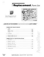
Summary of Contents for MP-2-SL

Page 1: ...s imperative that those responsible for the installation of this equipment as well as operating personnel read this manual and carefully follow all instructions and guidelines EQUIPMENT OPERATORS AND...

Page 2: ......

Page 3: ...eves 9 Installing the UV Lamps 10 Powering Up the Ultraviolet UV Unit 11 Monitoring Devices 11 UV Lamp Operational Display Panel 11 Running Time Meter 11 S 254 UV Optical Sensor 12 Setting the UV Mete...

Page 4: ...comply may result in severe or fatal electrical shock 6 Install the unit away from undue vibration that can damage the electrical components and UV lamps 7 Ensure all water connections flanges and co...

Page 5: ...bine the electrical components and the treatment chamber in one integral unit SL 10A This unit mounts vertically Inside the cabinet housing are the ballast and the UV treatment chamber The housing has...

Page 6: ...ed or repaired our option and returned to sender prepaid Before returning any part contact Aquafine Corporation for return authorization and shipping instructions This guarantee is void if the equipme...

Page 7: ...verheat problems described above where to install the unit Install the UV treatment unit in a horizontal position in a sheltered area with ample ventilation Ambient temperatures surrounding the unit s...

Page 8: ...e contact your local Aquafine represen tative or the factory directly wiring the unit A 1 2 conduit knockout 7 8 dia has been provided to attach a field installed junction box This box should be direc...

Page 9: ...8 plumbing schematic for all SL series ultraviolet treatment units MOUNTING BRACKET 2PLACES LED UV LAMP OPERATIONAL DISPLAY PANEL RUNNING TIME METER ModelSL 10A Service clearance required on this end...

Page 10: ...and o ring by placing the o ring into the internal relief of the compression nut below the threaded area The o ring should fit into the compression nut 9 Place the compression nut and o ring onto the...

Page 11: ...base into the rubber socket Push until you feel a firm bottomed out connection 8 Carefully slide the rubber boot portion of the lamp socket over the end of the lamp CAUTION DO NOT INSERT UV LAMPS WITH...

Page 12: ...hrough the system ensure there are no system leaks and no piping connection leaks All earth ground connections are properly made All lamp connections are properly made 1 Verify that all incoming power...

Page 13: ...lves Dry relay contacts are rated as follows 0 52 AMP 120 VAC 0 25 AMP 240 VAC If your application requires higher contact ratings use a slave relay Connection of peripheral equip ment is the responsi...

Page 14: ...empera turefallsto100 F 38 C HIGH TEMPERATURE HT UNITS The device automatically turns the UV lamps off when the water temperature reaches 170 F 77 C and auto matically turns the UV lamps back on when...

Page 15: ...r to one end of the lamp socket and the other end of the voltmeter of the opposite end of the lamp socket 7 Turn power on to the UV unit 8 Record the reading 9 Turn power off 10 Listed below please fi...

Page 16: ...less of the number of hours of operation due to normal operational degradation of the UV lamp CAUTION Prior to remov ing the cover to access the lamps and quartz sleeves you must release all pres sure...

Page 17: ...onnect ballast 9 Restore the power to the UV unit by turning the unit isolator switch to the ON position or by closing the upstream switch or breaker measuring performance Every UV treatment unit shou...

Page 18: ...or three and one half minutes reduce the flow to a reasonable stream of water not less than 50 of full flow Continue flowing to drain three additional minutes 4 Remove any temporary tubing used for fl...

Page 19: ...EPDM 4253 Viton 16458 Chemraz White 16600 Silicone 12967 2 LampSocket 16184 3 Running Time Meter 120 Volt 15843 4 Running Time Meter 240 Volt 15844 COMMON TO ALL SL 1 MP 2 SL APPLICATIONS 5 Quartz Sl...

Page 20: ...eduction Applications Size 15 Length 3052 14 ValidatedUVLampsDE185nmYellow TOC Reduction Applications Size 15 Length 16715 15 Quartz Sleeve 3150 16 Ballast 120Volt 4035 17 Ballast 240Volt 3493 18 Comp...

Reviews: