background image

4

To maintain your UV units warranty, please fill out
and mail the Warranty Registration Card in the back
pocket of this manual to Aquafine Customer Service.

The following installation and operating conditions are
considered hazardous or damaging to the equipment
and can compromise the ability of the Aquafine unit to
perform as intended.

ANY OF  THE FOLLOWING CONDITIONS WILL
VOID THE EQUIPMENT  WARRANTY.

1. Failure to connect proper electrical service to unit.

2. Failure to properly ground the unit.

3. Failure to eliminate excessive vibration, piping

movement, or water hammer.

4. Failure to exercise caution in the handling of the

sensitive and delicate components (such as lamps,
quartz sleeves, electronic boards, etc.) during
installation and/or maintenance procedures.

5. Failure to avoid excessive stops and starts. Not more

than three (3) on/off cycles per 24 hours of operation.

6. Operation of visibly damaged equipment.

7. Failure to avoid undue overhead piping stress which

can result in structural damage to the UV unit.
Limit the load to 10 lbs (4.54kg) per flange.

8. Use of components other than those provided or

authorized by Aquafine.

9. Failure to correct overhead piping connection leaks

or compression nut seal leaks which result in
damage to the electrical components.

10. Operating the unit without water flow.

SL series

The SL Series is the appropriate choice for many low
volume indoor applications because it offers a compact
footprint and easy installation. All three models
combine the electrical components and the treatment
chamber in one integral unit.

SL-10A

This unit mounts vertically. Inside the cabinet housing
are the ballast and the UV treatment chamber. The
housing has a front cover which allow access to all
interior components. On the side of the treatment unit is
a knockout for electrical input power.

SL-1

This unit mounts vertically. Inside the cabinet housing
are the ballast and the UV treatment chamber. The
housing has a front cover which allows access to all
interior components. On the side of the unit is a
knockout for electrical input power.

MP-2-SL

This unit mounts horizontally. Inside the electrical
housing are the ballast and two UV treatment chambers.
They operate serially, as this is the most efficient
design. The housing has a front cover which allows
access to all interior components. On the back is a
knockout for electrical input power.

treatment chamber

On both ends of the UV treatment chamber are gasketed
end plates which contain the stainless steel nipples,
compression nuts, O-rings and lamp socket retainer
assemblies. (This option is for RA finish cylinders).

Each treatment chamber is fitted with two raised-face
stainless steel flanges (in the case of the MP-2-SL, each
chamber has one flange each). The bottom flange is
always designated as the inlet, while the top flange is
the outlet.

Inside the inlet flange is a helical baffle that prevents
laminar flow and maximizes the unit’s performance.
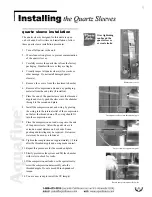
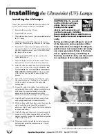
The quartz sleeves fit inside the UV treatment chamber
through the threaded nipples. The UV lamps fit inside
the quartz sleeves. The lamp sockets connect to the
lamps, providing a waterproof seal and a vibration-proof
grip.

Summary of Contents for MP-2-SL

Page 1: ...s imperative that those responsible for the installation of this equipment as well as operating personnel read this manual and carefully follow all instructions and guidelines EQUIPMENT OPERATORS AND...

Page 2: ......

Page 3: ...eves 9 Installing the UV Lamps 10 Powering Up the Ultraviolet UV Unit 11 Monitoring Devices 11 UV Lamp Operational Display Panel 11 Running Time Meter 11 S 254 UV Optical Sensor 12 Setting the UV Mete...

Page 4: ...comply may result in severe or fatal electrical shock 6 Install the unit away from undue vibration that can damage the electrical components and UV lamps 7 Ensure all water connections flanges and co...

Page 5: ...bine the electrical components and the treatment chamber in one integral unit SL 10A This unit mounts vertically Inside the cabinet housing are the ballast and the UV treatment chamber The housing has...

Page 6: ...ed or repaired our option and returned to sender prepaid Before returning any part contact Aquafine Corporation for return authorization and shipping instructions This guarantee is void if the equipme...

Page 7: ...verheat problems described above where to install the unit Install the UV treatment unit in a horizontal position in a sheltered area with ample ventilation Ambient temperatures surrounding the unit s...

Page 8: ...e contact your local Aquafine represen tative or the factory directly wiring the unit A 1 2 conduit knockout 7 8 dia has been provided to attach a field installed junction box This box should be direc...

Page 9: ...8 plumbing schematic for all SL series ultraviolet treatment units MOUNTING BRACKET 2PLACES LED UV LAMP OPERATIONAL DISPLAY PANEL RUNNING TIME METER ModelSL 10A Service clearance required on this end...

Page 10: ...and o ring by placing the o ring into the internal relief of the compression nut below the threaded area The o ring should fit into the compression nut 9 Place the compression nut and o ring onto the...

Page 11: ...base into the rubber socket Push until you feel a firm bottomed out connection 8 Carefully slide the rubber boot portion of the lamp socket over the end of the lamp CAUTION DO NOT INSERT UV LAMPS WITH...

Page 12: ...hrough the system ensure there are no system leaks and no piping connection leaks All earth ground connections are properly made All lamp connections are properly made 1 Verify that all incoming power...

Page 13: ...lves Dry relay contacts are rated as follows 0 52 AMP 120 VAC 0 25 AMP 240 VAC If your application requires higher contact ratings use a slave relay Connection of peripheral equip ment is the responsi...

Page 14: ...empera turefallsto100 F 38 C HIGH TEMPERATURE HT UNITS The device automatically turns the UV lamps off when the water temperature reaches 170 F 77 C and auto matically turns the UV lamps back on when...

Page 15: ...r to one end of the lamp socket and the other end of the voltmeter of the opposite end of the lamp socket 7 Turn power on to the UV unit 8 Record the reading 9 Turn power off 10 Listed below please fi...

Page 16: ...less of the number of hours of operation due to normal operational degradation of the UV lamp CAUTION Prior to remov ing the cover to access the lamps and quartz sleeves you must release all pres sure...

Page 17: ...onnect ballast 9 Restore the power to the UV unit by turning the unit isolator switch to the ON position or by closing the upstream switch or breaker measuring performance Every UV treatment unit shou...

Page 18: ...or three and one half minutes reduce the flow to a reasonable stream of water not less than 50 of full flow Continue flowing to drain three additional minutes 4 Remove any temporary tubing used for fl...

Page 19: ...EPDM 4253 Viton 16458 Chemraz White 16600 Silicone 12967 2 LampSocket 16184 3 Running Time Meter 120 Volt 15843 4 Running Time Meter 240 Volt 15844 COMMON TO ALL SL 1 MP 2 SL APPLICATIONS 5 Quartz Sl...

Page 20: ...eduction Applications Size 15 Length 3052 14 ValidatedUVLampsDE185nmYellow TOC Reduction Applications Size 15 Length 16715 15 Quartz Sleeve 3150 16 Ballast 120Volt 4035 17 Ballast 240Volt 3493 18 Comp...

Reviews: