


6
operating pressure
Standard units are rated for a maximum operating
pressure of 120 psig (8.24 bar).
If your unit has the High Pressure Modification option
(model number suffix “HP”) operating pressure may
increase to 150 psig (10.34 bar).
heat sanitization
For heat sanitization (temperatures exceeding 170°F
(77°C) up to a maximum of 194°F (90°C)), it is recom-
mended that stainless steel compression nuts be used in
place of CPVC compression nuts. During heat sanitiza-
tion the S-254 probe must be removed. (Adaptor
available for maintaining Hydrostatic seal during
sanitization.) The selection of the elastomers should
be considered.
intermittent operation
Never operate the unit without water flow.
Permanent
damage is caused to the UV lamp(s), electronic ballast
and related components without water flow.
Operating the ultraviolet unit without water flow
through the chamber automatically voids the war-
ranty.
If operated without water flow, the fluid within the
ultraviolet chamber will become hot causing the UV
lamp(s) to lose effectiveness. The heat can permanently
damage the ultraviolet lamp(s). The heat can also damage
the lamp ballast and related instrumentation.
Should the unit be used for specific batch flow opera-
tions, it can be turned “on” and “off” manually. Make
sure the unit is allowed to warm up for at least one
minute before use, and make sure the unit is turned
“Off” after each session. Do not exceed 3 on/off cycles
per 24 hour operation.
If you need help to determine the best method of operat-
ing your UV treatment unit under intermittent conditions,
contact your local representative or the factory.
An optional Temperature Safety Control Device is available
to prevent the overheat problems described above.
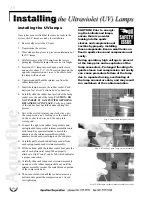
where to install the unit
Install the UV treatment unit in a horizontal position
in a sheltered area with ample ventilation. Ambient
temperatures surrounding the unit should be between
35
o
F (2
o
C) and 110
o
F (43
o
C). Should your requirements
differ, contact the factory for assistance.
As an ultraviolet UV treatment unit does not introduce
any chemical residue within the water, it is desirable to
install the unit as close as possible to the point-of-use in
order to avoid potential recontamination by discharge
pipes, fittings, etc. The base of the UV treatment unit
should be mounted on suitable support to avoid undue
strain on the unit or your related pipes and fittings.
Verify the location is free from vibration which could
be caused by proximity to heavy equipment, erratic or
improper pumps. Excessive vibration will damage
internal electrical components and cause premature
failure of the UV lamps.
Allow sufficient service access clearance. In making
your plumbing connections, provide unions, valves,
bypass and drain.
Please allow at least 40” of clearance on the lamp
changing end of the unit.
how to protect your unit
The location should be free from undue vibration which
could be caused by proximity to heavy equipment,
erratic or improper pumps. Excessive vibration will
damage internal electrical components and cause
premature failure of the UV lamps.
Limit overhead piping load to 10 lbs (4.54 kg) per
flange.
If your piping system is subject to impulse
pressure resulting in a “water hammer” condition, a
surge tank or other means must be provided to remove
this condition, otherwise the extreme momentary
pressure may rupture and fracture the quartz sleeves.
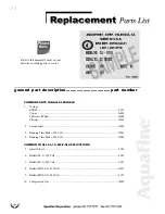
A parts check list was included when this unit
was shipped. Please refer to this list and note
that some parts are small and can be easily
overlooked when discarding packaging.
Summary of Contents for MP-2-SL
Page 2: ......


