Smartlog
- 42 -
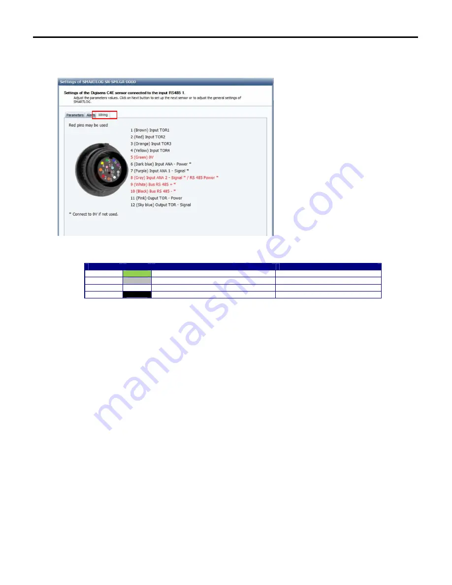
“Connection” tab:
The connection tab presents the wiring to be set up to implement the sensor. The signals in red are those used by the configuration.
The table below presents correspondences between the Smartlog and Ponsel digital sensors.
Pin number
Colours
Descriptions
Correspondences on Ponsel sensors
5
Green
0V
Black wire (3)
8
Grey
Signal* analogue input 2 / Power supply RS485
Red wire (1)
9
White
RS485 D+
White wire (5)
10
Black
RS485 D-
Green wire (4)
Once the configuration has been set, click next to set the general parameters and communications (see 8.5 General settings and communications
management).
Summary of Contents for SMARTLOG
Page 1: ...SMARTLOG User manual Version 1 0 ...
Page 2: ...Smartlog 2 ...


