background image

Rise Digital Bath

installation instuctions

page 6

Step-by-step instructions

70mm

This product must be installed by a competent person in accordance with

the current Water Supply Regulations.

In addition to the guide below it is essential that the written instructions

overleaf are read and understood and that you have all the necessary

components (shown overleaf) before commencing installation.

The Rise Digital bath system is supplied with universal fixings intended

to secure it to a suitable wall.

!

90mm

4

4

5

m

m

2

7

0

m

m

350mm

2

6

5

m

m

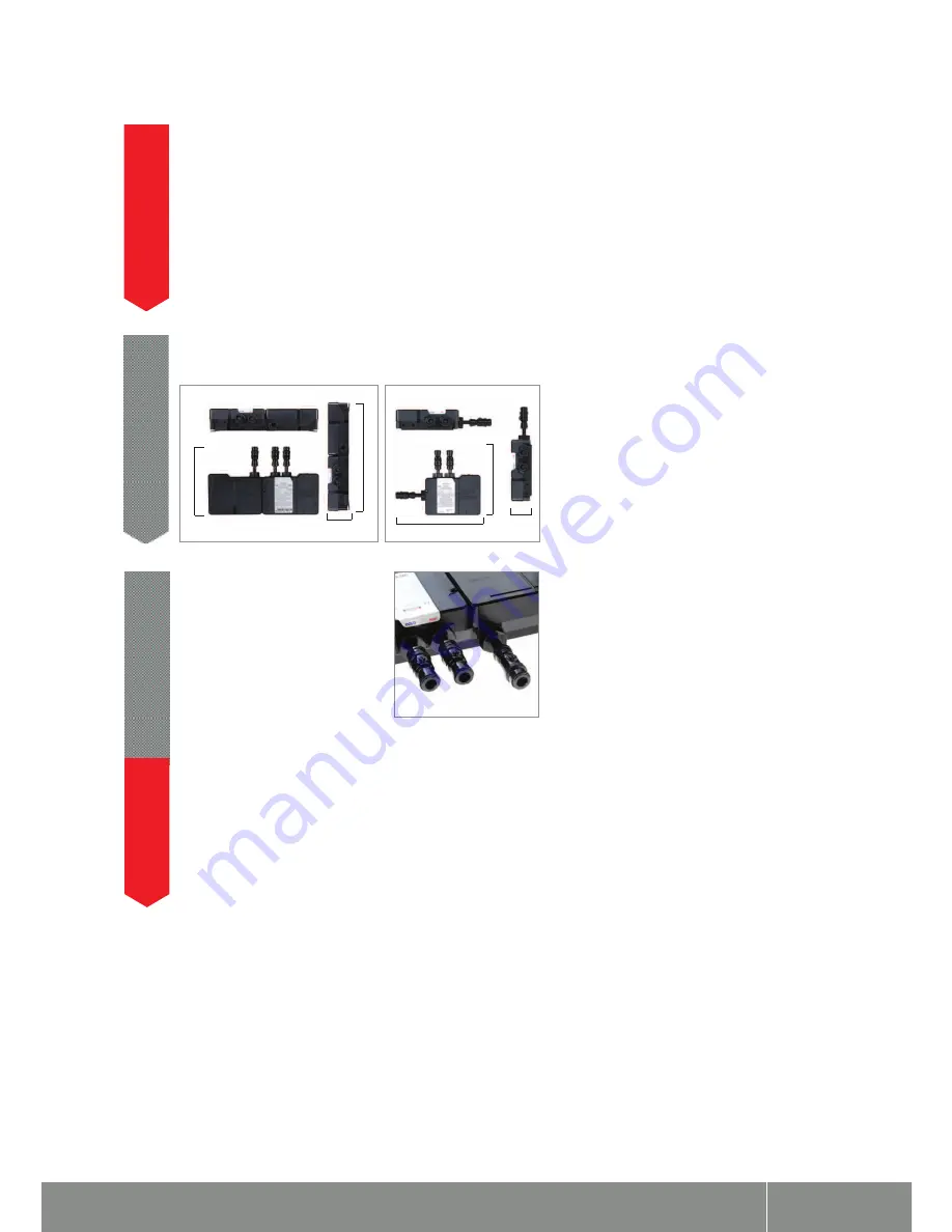
To ensure safe operation and installation of this product, the

processor MUST be installed in one of the orientations shown.

1

Isolation valves are supplied with the

Digital processor and must be fitted on

both inlets and the blended water outlet.

All pipe work should be run in 15mm

pipe. All pipe work should be supported.

For externally pumped gravity fed

installations, 22mm pipe work should

be run as close to the processor as possible

before reducing down to 15mm.

2

The inlet supply centres are 48mm. The inlet supply centres

deviate from EN1111 and EN1287, but are deemed to be a

special case.

Please note arrow on isolation valve to indicate direction of flow.

Compression fittings should not be used on the inlet and outlet

spigots and may affect the warranty if fitted.

!

Summary of Contents for RSDB1X

Page 1: ...er Responsibility Regulation 2004 This product is outside the scope of the European Waste Electrical and Electronic Equipment Directive as interpreted within the UK In the UK this product can therefore be disposed of through commercial non WEEE waste facilities The original manufacturer does not accept any liability under the WEEE directive ...

Page 2: ...gital Bath installation instuctions page 2 Bath system Rise Digital Bath with overflow filler Rise Digital Bath with overflow filler HP Combi RSDB1X Rise Digital Bath with overflow filler Gravity Pumped RSDB2X ...

Page 3: ...Rise Digital Bath installation instuctions page 3 Components HP Combi Components Gravity Pumped ...

Page 4: ...h the product Installation of Digital pumped processor for gravity stored systems The Rise Digital pumped bath system is designed to operate up to maximum static pressure of 100kPa 1 bar 10 metres head 14 5psi Under no circumstances must the pumped processor be connected directly to the water main or in line with another booster pump The minimum actual capacity of the cold water storage cistern sh...

Page 5: ... working parts of this unit All soldering must be completed and the pipe work thoroughly flushed out in accordance with current Water Supply Regulations prior to connection of the product After installation Familiarise the end user with the Rise Digital operation and hand them this guide Complete and post the guarantee card or register online at www aqualisa co uk ...

Page 6: ...tion and installation of this product the processor MUST be installed in one of the orientations shown 1 Isolation valves are supplied with the Digital processor and must be fitted on both inlets and the blended water outlet All pipe work should be run in 15mm pipe All pipe work should be supported For externally pumped gravity fed installations 22mm pipe work should be run as close to the process...

Page 7: ...D IN THE LOFT SPACE THE ROUTE TO AND THE AREA AROUND THE PROCESSOR MUST BE BOARDED TO ENSURE SAFE WORKING ENVIRONMENT Place the Digital processor on a solid mounting surface and place the fixing feet into suitable positions Mark then drill and prepare suitable fixings before securing the processor to the mounting surface using the screws provided 4 Flush out the hot and cold supply pipes 5 The max...

Page 8: ...mastic groove on the back of the mounting plate and press into position onto the finished wall surface Ensure the data cable is held securely by the narrow middle slot of the mounting plate and fix to the wall using the screws provided 10 Plug the data cable into the rear of the controller and push fully home Slide the controller assembly onto the mounting plate Secure the controller to the back p...

Page 9: ...damage from vermin The data cable and power lead should also be clipped in place with P clips or similar to avoid accidents BEFORE ANY ELECTRICAL ADJUSTMENT IS ATTEMPTED THE ELECTRICITY SUPPLY MUST BE TURNED OFF AT THE MAINS SWITCH ELECTRICAL INSTALLATION MAY ONLY BE CARRIED OUT BY A QUALIFIED PERSON Connect the low voltage data cable into the socket adjacent to the temperature adjuster as indicat...

Page 10: ...should not be selected for bath systems fitted to combination boilers PUMPED PROCESSORS Pumped processors fitted to gravity systems may be set to NORMAL GRAVITY or for water economy ECO flow rate modes N B We recommend the processor is set to NORMAL GRAVITY mode WHEN MAKING ANY ADJUSTMENT TO THE PROCESSOR SETTINGS THE POWER MUST BE ISOLATED Run the bath at maximum temperature factory pre set to 45...

Page 11: ...water level has reached the desired height press the start stop button to turn off the bath fill 2 The amended run time has been recorded 3 The Rise Digital bath product has a factory set maximum run time of 12 minutes If required this can be adjusted anywhere from 1 second up to 30 minutes to suit the site conditions by adopting the following procedure Due to the performance characteristics of co...

Page 12: ... installation guide for full fitting instructions Aqualisa Products Limited reserves the right to revoke the guarantee if an overhead shower kit system is fitted with a bath controller The bath overflow filler is suitable for baths up to a maximum thickness of 24mm Carefully unscrew and remove the overflow filler outlet from the body assembly and set aside 1 Carefully unscrew and remove the bath w...

Page 13: ... to the body assembly 7 Remove the relevant inlet blanking plug and attach the flexible hose to the blended inlet connection 8 Connect the flexible hose to the blended supply pipe ensuring suitable non restrictive double check valves are fitted in line with current Water Supply Regulations not supplied 9 Waste pipe extension kit If required for larger baths a 900mm waste pipe conversion kit is ava...

Page 14: ...ctions page 14 Remove the clamping nut and sealing washer from the waste pipe and set aside 2 Carefully pull the waste pipe away from the outlet assembly 3 Reassemble the unit using the longer waste pipe by reversing the above procedure 4 ...

Page 15: ...utton Bath Top up Rise Digital Bath features a Top up button wich provides a method of topping up your bath at the desired temperature at a minimum flow rate To operate the bath in Top up mode 1 Turn the temperature dial to the required setting 2 Press the Top Up button to begin topping up the bath The bath will run for 1 minute before stopping automatically N B The bath fill can be stopped at any...

Page 16: ...llation compatible with pumped processor T Typical HP system installation compatible with standard processor Typical thermal storage unit system installation compatible with standard processor T Typical installations Supply Pressure reducing valve if required 10m max Digital shower control Supply Vent and draw off pipe to hot water Underside of cistern Hot water cylinder NB 1 5 bar MINIMUM pump ra...

Page 17: ...of Ireland 01 844 3212 Brochure Hotline 0800 652 3669 Website www aqualisa co uk Email enquiries aqualisa co uk Please note that calls may be recorded for training and quality purposes The company reserves the right to alter change or modify the product specifications without prior warning Registered Trademark Aqualisa Products Limited Part No 700067 Issue 01 Jan 12 ...

Reviews: