background image

SHARK

TX

& SHARK

TXP

MULTI-PARAMETER

TRANSMITTER USER’S MANUAL

AquaMetrix Inc.

1245 Maple Hill Ct., Unit 7

Newmarket, ON

Canada, L3Y 9E8

Tel: (800) 742-1413

(905) 954-0841

Fax: (905) 954-0415

www.aquametrix.com

N116-35 Rev 3

A57-24

Summary of Contents for SHARK TX

Page 1: ...SHARKTXP MULTI PARAMETER TRANSMITTER USER S MANUAL AquaMetrix Inc 1245 Maple Hill Ct Unit 7 Newmarket ON Canada L3Y 9E8 Tel 800 742 1413 905 954 0841 Fax 905 954 0415 www aquametrix com N116 35 Rev 3...

Page 2: ...Paddle Wheel Flow Sensor connection setup 10 4 20mA Isolated Output 11 Section 4 Using the Transmitter in pH Mode 12 LCD Menu 13 28 Section 5 Using the Transmitter in ORP Mode 29 LCD Menu 30 44 Sectio...

Page 3: ...in the Utilities menu To return the Shark to its factory settings the user must re select the current meter type from the meter selection menu function This will override all set points and return al...

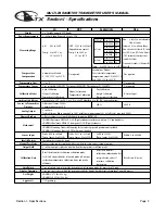
Page 4: ...ter Differential Sensor 3000 ft 300 ft 2000 ft Distance Combination Sensor 10 ft Analog Output 4 to 20mA Isolated Output Range expand 0 to 100 of full scale min segment 10 of full scale max load 800 M...

Page 5: ...e and report any problems immediately 2 2 Location Locate the transmitter close to the sensor The list below gives typical maximum distances for various sensors Refer to the sensor specifications for...

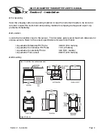
Page 6: ...ensions are shown in fig 2 1 and 2 2 EXTERNAL PANEL GASKET QTY 1 SCREW 4 40 X 3 4 QTY 4 NUT 4 40 QTY 4 PANEL CUSTOMER SUPPLIED PANEL CUSTOMER SUPPLIED EXTERNAL PANEL GASKET QTY 1 SCREW 1 4 20 X 2 1 2...

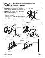
Page 7: ...de diameter of 1 30 33mm for example 1 CPVC pipe and a maximum of 2 375 60mm for example 2 CPVC pipe DIN Rail Mount The SHARKTXP can be DIN rail mounted or panel mounted See figure 2 3 figure 2 7 MIN...

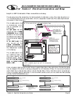
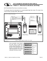
Page 8: ...t seals These must be left in unused holes to maintain the NEMA 4X integrity Use approved conduit hubs to connect the conduit connect these to the conduit before connecting to the enclosure 3 2 Power...

Page 9: ...ep through the LCD menus to select the probe in the order shown The first two steps may be skipped if the meter is already con figured for pH or ORP and a Differential Probe When using a pH probe it i...

Page 10: ...obe If a two wire pH probe is used which has no temperature sensor ensure that the Temp Comp Override is set to same temper ature as the buffer before calibrating If a two wire ORP probe is used you c...

Page 11: ...EMP COMP CURVE setup default is 1 8 deg C This is accept able for most process appli cations If your process is significantly different from this change the setting in the TEMP COMP CURVE menu The dra...

Page 12: ...e connected step through the LCD menus to select the sensor in the order shown The Sensor K factor pulses per U S Gallon is usually printed on the side of the sensor or on a label attached to the sens...

Page 13: ...ONS pH 4 15 ORP 5 14 Conductivity 6 16 Flow 7 14 The Transmitter has a single 4 to 20mA output electrically isolated from the ground The output can source current into a resistive load Maximum resista...

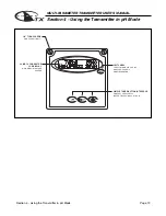
Page 14: ...tion 4 Using the Transmitter in pH Mode Page 12 SIMPLE THREE BUTTON INTERFACE FOR FAST EASY SETUP REFER TO SECTIONS 4 0 TO 4 15 2 LINE 16 CHARACTER LCD DISPLAY MAIN MENU INTERFACE SCREEN 1 4 TURN SCRE...

Page 15: ...C 4 14 SEC 4 9 SEC 4 10 SEC 4 11 SEC 4 6 SEC 4 7 SELECT TYPE OF TEMP SENSOR SEC 4 8 pH PROBE RUN MODE SEC 4 3 UP NOTE PRESS THE AND KEYS TOGETHER TO GO IMMEDIATELY BACK TO RUN MODE DOWN SELECT TYPE OF...

Page 16: ...e the measurement The controller will read the pH value averaging a number of results to get a stable calibration value Place the probe in the first buffer solution be sure to clean and rinse the Prob...

Page 17: ...e calibration the estimated probe efficiency and the probe temperature When complete the controller will report the measured value When complete the controller will report the measured value Press the...

Page 18: ...function Use the and to adjust the reading until it agrees with the known temperature of the probe Press the key to accept the reading and move to the store function T FACTOR SHIFTED will be displayed...

Page 19: ...s the run mode The output will then revert back to the previous On line state The 4 20 mA output will track the change in process value RUN MODE UP NOTE PRESS THE AND KEYS TOGETHER TO GO IMMEDIATELY B...

Page 20: ...MODE Press the key to initialize the controller as a Flow meter Press the key to initialize the controller as a Conductivity meter The Meter Selection menu is used to select the meter type that the c...

Page 21: ...allow the user to select whether the probe is a 2 or 4 wire combination probe or a 5 wire differential probe RUN MODE UP NOTE PRESS THE AND KEYS TOGETHER TO GO IMMEDIATELY BACK TO RUN MODE DOWN Use th...

Page 22: ...ELY BACK TO RUN MODE DOWN Then press the key to store the selection and return to the TEMP UNIT Selection Menu Not stored Stored the Y character Use the or to select C or F Press the key to accept the...

Page 23: ...store function Then press the key to store the selection and return to the TEMP SENSOR Selection Menu Stored TEMP SENSOR allows the user to select the type of temperature sensor used the in the probe...

Page 24: ...URN setting Press the key once which will move the cursor to the ON or OFF text Use the or keys to select either ON or OFF Press the key once which will move the cursor back to the RH side of the disp...

Page 25: ...HE AND KEYS TOGETHER TO GO IMMEDIATELY BACK TO RUN MODE DOWN With N selected pressing the key will NOT store the selection but simply return to the T Comp Override Menu This function is useful if you...

Page 26: ...view the current selection without making any changes Not stored RUN MODE Use the and to adjust the damping time the default setting is 0 seconds The setting can be adjusted from 0 to 10 seconds Then...

Page 27: ...WN DOWN DOWN DOWN The FIRMWARE REV menu allows the user to see what revision of the firmware is currently installed in the controller This is a Read Only menu item RUN MODE UP NOTE PRESS THE AND KEYS...

Page 28: ...TO GO IMMEDIATELY BACK TO RUN MODE DOWN 1st POINT PH 7 00 INPUT FROM PROBE 19 mV Calculated efficiency based on 2 point calibration 91 Calculated slope based on 2 point calibration 59 16 mV pH Probe...

Page 29: ...T FIRMWARE REV 7 15pH 25 0C UTILITIES CALIBRATION TEMP 331 PROBE 18mV RUN MODE Troubleshooting a pH probe using the sensor input Sensor input displays the uncompensated sensor input data The pH probe...

Page 30: ...7 0 to 14 0 Note that the span can reversed in that 4 mA can be set to a high pH value and 20 mA can be set to a low pH value effectively reversing the control direction Use the and keys to change th...

Page 31: ...NUAL Section 5 Using the Transmitter in ORP Mode SIMPLE THREE BUTTON INTERFACE FOR FAST EASY SETUP REFER TO SECTIONS 5 0 TO 5 13 2 LINE 16 CHARACTER LCD DISPLAY MAIN MENU INTERFACE SCREEN 1 4 TURN SCR...

Page 32: ...ED PROBE DATA SEC 5 13 SEC 5 8 SELECT TYPE OF TEMP SENSOR SEC 5 7 SEC 5 9 SEC 5 10 SEC 5 5 SEC 5 6 ORP PROBE RUN MODE SEC 5 2 UP NOTE PRESS THE AND KEYS TOGETHER TO GO IMMEDIATELY BACK TO RUN MODE DOW...

Page 33: ...will display the mV value and the probe temperature for 5 seconds If the T DISPLAY O R is enabled the display will show If the calibration is OK use the key to move the cursor over the Y text and pre...

Page 34: ...ion Use the and to adjust the reading until it agrees with the known temperature of the probe Press the key to accept the reading and move to the store function T FACTOR SHIFTED will be displayed for...

Page 35: ...l the operator enters the run mode The output will then revert back to the previous On line state The 4 20 mA output will track the change in process value RUN MODE UP NOTE PRESS THE AND KEYS TOGETHER...

Page 36: ...N MODE Press the key to initialize the controller as a Flow meter Press the key to initialize the controller as a Conductivity meter The Meter Selection menu is used to select the meter type that the...

Page 37: ...allow the user to select whether the probe is a 2 or 4 wire combination probe or a 5 wire differential probe RUN MODE UP NOTE PRESS THE AND KEYS TOGETHER TO GO IMMEDIATELY BACK TO RUN MODE DOWN Use th...

Page 38: ...ATELY BACK TO RUN MODE DOWN Then press the key to store the selection and return to the TEMP UNIT Selection Menu Not stored Stored the Y character Use the or to select C or F Press the key to accept t...

Page 39: ...he store function Then press the key to store the selection and return to the TEMP SENSOR Selection Menu Stored TEMP SENSOR allows the user to select the type of temperature sensor used in the probe T...

Page 40: ...ETURN setting Press the key once which will move the cursor to the ON or OFF text Use the or keys to select either ON or OFF Press the key once which will move the cursor back to the RH side of the di...

Page 41: ...the selection but simply return to the T Disp Override Menu This function is useful if you wish to view the current selection without making any changes If you wish to save the setting press the key t...

Page 42: ...sh to view the current selection without making any changes Not stored RUN MODE Use the and to adjust the damping time the default setting is 0 seconds The setting can be adjusted from 0 to 10 seconds...

Page 43: ...DOWN DOWN DOWN DOWN The FIRMWARE REV menu allows the user to see what revision of the firmware is currently installed in the controller This is a Read Only menu item RUN MODE UP NOTE PRESS THE AND KEY...

Page 44: ...view the data collected during the last calibration RUN MODE If the Temperature Display Override is ON Section 5 10 the display will show Press to view the first Calibration Data screen 1st POINT 600...

Page 45: ...ated process data from the probe This is a Read only menu item The top line shows the mV input from the probe The bottom line shows the actual value of the temperature sensor in ohms Press to view the...

Page 46: ...g of 200mV to 800mV Note that the span can be reversed in that 4 mA can be set to a high mV value and 20 mA can be set to a low mV value effectively reversing the control direction Use the and keys to...

Page 47: ...NUAL Section 6 Using the Transmitter in Conductivity Mode SIMPLE THREE BUTTON INTERFACE FOR FAST EASY SETUP REFER TO SECTIONS 6 0 TO 6 16 2 LINE 16 CHARACTER LCD DISPLAY MAIN MENU INTERFACE SCREEN 1 4...

Page 48: ...E DATA SEC 6 12 SETUP TEMP SEC 6 11 SEC 6 10 SEC 6 6 SEC 6 9 SEC 6 7 SEC 6 8 TEMP SENSOR FROM MENU RANGE RUN MODE SEC 6 3 UP NOTE PRESS THE AND KEYS TOGETHER TO GO IMMEDIATELY BACK TO RUN MODE DOWN VE...

Page 49: ...correct press the key which will return back to the Manual Cal Cond menu DOWN RUN MODE UP NOTE PRESS THE AND KEYS TOGETHER TO GO IMMEDIATELY BACK TO RUN MODE DOWN Place the cell in the buffer solution...

Page 50: ...d menu DOWN NOTE ACCELERATOR KEYS Pressing the or key once will change the value by the smallest digit Holding the key down will cause the value to change at an increasing rate until the key is releas...

Page 51: ...h will move the cursor over the least significant digit of the temperature display RUN MODE DRY CAL COND STORE Y N TEMP CALIBRATION STORE Y N TEMP CALIBRATION TEMP CALIBRATION 25 0C T FACTOR SHIFTED 2...

Page 52: ...perator enters the run mode The output will then revert back to the previous On line state The 4 20 mA output will track the change in process value RUN MODE UP NOTE PRESS THE AND KEYS TOGETHER TO GO...

Page 53: ...menu RUN MODE Press the key to initialize the controller as a Flow meter Press the key to initialize the controller as a Conductivity meter The Meter Selection menu is used to select the meter type t...

Page 54: ...lection without making any changes Not stored RUN MODE UP NOTE PRESS THE AND KEYS TOGETHER TO GO IMMEDIATELY BACK TO RUN MODE DOWN Then press the key to store the selection and return to the COND RANG...

Page 55: ...RUN MODE DOWN Then press the key to store the selection and return to the TEMP UNIT Selection Menu Stored Or press the key to highlight the Y character TEMP UNIT allows the user to select either Degr...

Page 56: ...ND KEYS TOGETHER TO GO IMMEDIATELY BACK TO RUN MODE DOWN Not stored Stored Or press the key to highlight the Y character Press the key once which will move the cursor over to the sensor type Once the...

Page 57: ...rgets to return back to run mode the controller will not be left in an offline state If for some reason the user would like to remain in the menu mode for extended periods of time the AUTO RETURN func...

Page 58: ...N MODE Press the key to accept the reading and move to the store function Press the key once which will move the cursor back to the RH side of temperature display Then press the key to store the selec...

Page 59: ...key to highlight the Y character Then press the key to store the selection and return to the Display Damping Menu Press the key once which will move the cursor back to the RH side of the display Press...

Page 60: ...he RH side of the display The Temperature Compensation Curve setting allows the user to select the temperature compensation to match a specific process The variation of Conductivity versus Temperature...

Page 61: ...13 DOWN DOWN DOWN DOWN DOWN RUN MODE NOTE PRESS THE AND KEYS TOGETHER TO GO IMMEDIATELY BACK TO RUN MODE The FIRMWARE REV menu allows the user to see what revision of the firmware is currently install...

Page 62: ...25 2 C Calculated Cell Constant Conductivity of Buffer Input Resistance Press to view the next Calibration Data screen Press to view the first Calibration Data screen TYPICAL DISPLAYS FOR MANUAL CAL C...

Page 63: ...ata The Sensor Input Menu allows the user to view real time uncompensated process data from the conductivity cell This is a Read only menu item This Live Data screen is useful for trouble shooting pur...

Page 64: ...ucivity value effectively reversing the control direction If you wish to change the setting press the key once which will move the cursor to the first character of the value to be changed Use the and...

Page 65: ...tion 7 Using the Transmitter in Flow Mode Page 63 SIMPLE THREE BUTTON INTERFACE FOR FAST EASY SETUP REFER TO SECTIONS 7 0 TO 7 14 2 LINE 16 CHARACTER LCD DISPLAY MAIN MENU INTERFACE SCREEN 1 4 TURN SC...

Page 66: ...TOGETHER TO GO IMMEDIATELY BACK TO RUN MODE DOWN TO ZERO SEC 7 8 RESET TOTALIZER SETUP DISPLAY AND OUTPUT RESPONSE TIME ENABLE TIME OUT SETUP OF UNITS SETUP OF UNITS SEC 7 4 SEC 7 7 SEC 7 6 FROM MENU...

Page 67: ...ew K Factor value quickly DOWN UP The K Factor can be set anywhere from 0 5000 pulses per U S Gallon to 1500 0 pulses per U S Gallon RUN MODE Press to store the calibration data and return back to the...

Page 68: ...y once which will move the cursor over the least digit of the simulated process value Use the and keys to change the simulated process value Manual Test Mode is used to simulate a process reading in o...

Page 69: ...RUN MODE Press the key to initialize the controller as a Flow meter Press the key to initialize the controller as a Conductivity meter The Meter Selection menu is used to select the meter type that t...

Page 70: ...gain use the or keys to select the appropriate text character then press the key to move the cursor to the RH position Press the key to accept the setting and move to the custom multiplier setting The...

Page 71: ...LED display UP NOTE PRESS THE AND KEYS TOGETHER TO GO IMMEDIATELY BACK TO RUN MODE DOWN Not stored With N selected pressing the key will NOT store the selection but simply return to the UNITS OF TIME...

Page 72: ...will move the cursor back to the RH side of the display To change the MENU RETURN setting Press the key once which will move the cursor to the ON or OFF text Use the or keys to select either ON or OF...

Page 73: ...Press the key to accept the setting and move to the store function Press the key once which will move the cursor over the seconds digit The Display Damping menu allows the user to adjust the rate at...

Page 74: ...the Flow totalizer to zero Note that once complete this action cannot be reversed The accumulated total will be erased permanently UP NOTE PRESS THE AND KEYS TOGETHER TO GO IMMEDIATELY BACK TO RUN MOD...

Page 75: ...N DOWN DOWN DOWN DOWN RUN MODE UP NOTE PRESS THE AND KEYS TOGETHER TO GO IMMEDIATELY BACK TO RUN MODE DOWN The FIRMWARE REV menu allows the user to see what revision of the firmware is currently insta...

Page 76: ...DIATELY BACK TO RUN MODE DOWN The Calibration Data menu is a read only screen which allow the user to view the K factor entered during the last calibration This screen shows the K factor entered durin...

Page 77: ...AND KEYS TOGETHER TO GO IMMEDIATELY BACK TO RUN MODE DOWN Press to view the Sensor Input data Press to return to the menu The Sensor Input Menu allows the user to view real time signals from the probe...

Page 78: ...Total is a running total of all the volume units that have been accumulated by the controller It starts at zero when new and can only be set to zero at the factory This is a read only screen UP NOTE...

Page 79: ...en It is used to indicate how many times the Permanent and Resetable Totalizers have rolled over during the life of the controller Press to view the Totalizer Rollovers to date PER indicate the number...

Page 80: ...y once which will move the cursor back to the RH side of the display If you wish to change the setting press the key once which will move the cursor to the first character of the value to be changed D...

Page 81: ...r P585 COMBINATION no temp sensor P585K 1 COMBINATION Pt 1000 RTD P585K 2 COMBINATION 300 P585 BNC COMBINATION no temp sensor P565 COMBINATION no temp sensor P565L COMBINATION no temp sensor Model Pro...

Page 82: ...12 months from the date of shipment from our facility A warranty claim will not be honored if defects are not reported within the warranty period or if AquaMetrix determines that defects or damages a...

Reviews: