background image

23

ONE | USE AND INSTALLATION GUIDE 

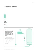
CONNECT POWER

9

Power 
adaptor

1 piece

Connect power to ONE 
by pushing the cord 
connected to ONE into 
the power adaptor and 
tighten. 

If desired, the power 
adaptor can be mounted 
to a wall or cabinet with 
two screws. Screws 
for this step are not 
included.

1/1

9

Summary of Contents for One

Page 1: ...USE AND INSTALLATION GUIDE ...

Page 2: ...DRAIN INSTALLATION 12 INLET INSTALLATION 14 FAUCET INSTALLATION 19 PURE WATER INSTALLATION 21 CONNECT POWER 23 COMPLETE THE INSTALLATION 24 REPLACEMENT OF CARTRIDGES 25 SYSTEM SPECIFICATIONS 29 For installation manuals in other languages please contact the place where you bought your ONE or visit aquaporin com installation ...

Page 3: ...3 ONE USE AND INSTALLATION GUIDE DIMENSIONS AND WEIGHT Net weight 5 7 kg Gross weight 13 5 kg 42 cm 13 2 cm 46 cm ...

Page 4: ... 1 piece 2 Pressure reducer 1 piece 3 Push in reducer 1 piece 4 PE pipe 1 4 OD 5 m 16 feet 5 PE pipe 3 8 OD 2 m 6 5 feet ONE Specifications sheet LIST OF INCLUDED COMPONENTS 1A Drain clamps 1 pair 1B Screw nut 2 pieces 1C Gasket 1 piece DRAIN CLAMP KIT ...

Page 5: ...wrench 1 piece Tools required for installation 11 mm key or flexible spanner Flat and Phillips screwdriver Pincer Electrical drilling machine 6 mm and 12 mm drill FAUCET KIT 11F T piece with ball valve 1 piece 11A Faucet 1 piece 11B Spacer 1 piece 11C Upper white gasket 1 piece 11D Lower black gasket 1 piece 11E Plastic nut 1 piece ...

Page 6: ...DIYers can independently conduct the installation work providing they possess the necessary skills and experience Installation specialists are authorized to conduct installation work in line with existing regulations Cleaning and maintenance If you leave the system idle for more than three days it is recommended to disconnect the power and close the inlet water ball valve When using the device aga...

Page 7: ... the indicator turns off The machine will recover normal operation after connecting to power again SAFETY INSTRUCTIONS If the inlet water tap water connection to the device is closed disconnect the power supply to prevent that no water pressure will be detected The device will recover normal operation after connecting to power again When there is no water supply or the pipe is under repair please ...

Page 8: ... the hazards involved The appliance can be used by children aged 8 and above as well as people with reduced physical sensory or mental capacities or lack of experience and or knowledge if they are supervised or have been instructed how to safely use the appliance and understand the resultant risks Children must be supervised All safety and warning information and handling instructions in the insta...

Page 9: ...9 ONE USE AND INSTALLATION GUIDE INSTALLATION SCHEME Wastewater Inlet water Pure water Water source Inlet water tap water Pure water Main unit Faucet Drain pipe Wastewater ...

Page 10: ...re you start please be sure to clean your hands thoroughly as well as any tools used during the installation of your ONE Before installation ensure that the cold water valve is turned off closed TURN OFF The installation will take approximately one hour ...

Page 11: ... the grey release collar 2 You can now pull the plug upwards with your fingers Note that the length of the 1 4 OD PE pipe is 5 meters This length is to be used for multiple connections so use only what you need for each connection and save the remaining for later installation steps When you cut the PE pipes be aware that the pipe is not compressed when you insert it into connections 1 2 Note that ...

Page 12: ...LLATION 1A Drain clamps 1 pair 1B Screw nut 2 pieces 1C Gasket 1 piece DRAIN CLAMP KIT 4 PE pipe 1 4 OD Cut length to fit 7 Small retaining ring 2 piece Drill ø 6 mm 15 64 1A 1B 1C Add the gasket between the drain clamps and the drain pipe Gasket 2 5 ...

Page 13: ...ximately 2 cm will be going into your drain pipe Tighten the clamp with the Phillips screwdriver 2 cm 7 4 Wastewater 5 5 4 Cut the 1 4 OD PE pipe to fit the installation and insert it into the wastewater connection on the machine Push in the small retaining ring between the grey ring and the machine 7 ...

Page 14: ...ET INSTALLATION 11F T piece with ball valve 1 piece 2 Pressure reducer 1 piece 3 Push in reducer 1 piece 4 PE pipe 1 4 OD Cut length to fit 5 PE pipe 3 8 OD Cut length to fit 7 Small retaining ring 3 pieces 8 Large retaining ring 2 pieces ...

Page 15: ...5 ONE USE AND INSTALLATION GUIDE INLET INSTALLATION 1 7 2 7 3 7 Unscrew the nut from the ball valve Insert the 1 4 OD pipe onto the ball valve Tighten the nut with a 11 mm key or a flexible spanner 11F 4 ...

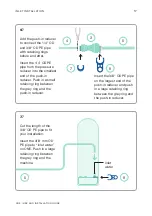
Page 16: ...and the pressure reducer Insert a new 5 cm piece of 1 4 OD PE pipe at the other end of the pressure reducer and place a small retaining ring between the blue ring and the pressure reducer Note that the direction of the pressure reducer The arrow should be pointing towards the ONE away from the inlet water ball valve Cold water pipe 2 7 7 Connect the T piece with ball valve on your cold water pipe ...

Page 17: ... in a small retaining ring between the grey ring and the push in reducer Cut the length of the 3 8 OD PE pipe to fit your installation Insert the 3 8 mm OD PE pipe to inlet water on ONE Push in a large retaining ring between the grey ring and the machine 7 8 8 Insert the 3 8 OD PE pipe on the largest end of the push in reducer and push in a large retaining ring between the grey ring and the push i...

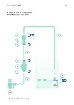
Page 18: ...18 ONE USE AND INSTALLATION GUIDE Complete order of components for installation of inlet water 11F INLET INSTALLATION 3 2 7 7 7 4 5 4 8 8 Inlet water ...

Page 19: ...19 ONE USE AND INSTALLATION GUIDE FAUCET INSTALLATION 11A Faucet 1 piece 11B Spacer 1 piece 11C Upper white gasket 1 piece 11D Lower black gasket 1 piece 11E Plastic nut 1 piece FAUCET KIT ...

Page 20: ... AND INSTALLATION GUIDE FAUCET INSTALLATION Drill ø 12 mm 15 32 Drill a hole adjacent to your regular faucet 1 3 2 3 11A 11B 11C 11E 11D Assemble and tighten with your hands no use of tools Remove the rubber cover from the faucet ...

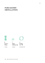
Page 21: ...21 ONE USE AND INSTALLATION GUIDE PURE WATER INSTALLATION 6 Push in fitting 1 piece 7 Small retaining ring 3 pieces 4 PE pipe 1 4 OD Cut length to fit ...

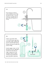
Page 22: ...n the grey ring and the push in fitting Insert a new piece of the 1 4 OD PE pipe in the other end of the push in fitting and push in a small retaining ring between the grey ring and the push in fitting Cut the length of the 1 4 OD PE pipe to fit your installation and insert it into the pure water connection on the machine Push in a small retaining ring between the grey ring and the machine ...

Page 23: ...WER 9 Power adaptor 1 piece Connect power to ONE by pushing the cord connected to ONE into the power adaptor and tighten If desired the power adaptor can be mounted to a wall or cabinet with two screws Screws for this step are not included 1 1 9 ...

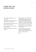
Page 24: ...mber to flush before consuming the water After installation of your ONE or after replacing the cartridges the system must be flushed before consuming the water This is done by leaving the faucet open for 30 minutes Note that the first water coming out will be black Check that none of your connections leak and the that you have no breaks on the PE pipe You will be left with one spare part which is ...

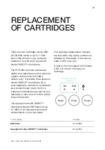
Page 25: ...onsidered as a precautionary step to remove bacterial contamination as well as any bad taste or odor and to further polish the purified water The Aquaporin Inside DWRO membrane inside ONE filters out up to 99 of all dissolved solids and contaminants in your tap water The cartridge replacement intervals are indicative only as the condition is affected by the quality of the source water which may va...

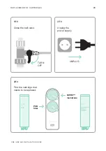
Page 26: ...E USE AND INSTALLATION GUIDE REPLACEMENT OF CARTRIDGES Close the ball valve Unplug the power supply Find the cartridge that needs to be replaced 1 10 2 10 3 10 TURN OFF UNPLUG PCB filter DWRO membrane PCB RO ...

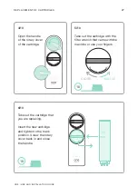
Page 27: ...tridge Take out the cartridge with the filter wrench that came with the machine or use your fingers Take out the cartridge that you are replacing Insert the new cartridge and tighten to the mark position Screw the rotary cover back in and close the handle 4 10 5 10 6 10 RO PCB PCB PCB RO 10 RELESE CLOSE 10 ...

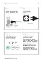
Page 28: ...sh Power Remember to flush before consuming the water After replacing the PCB filter open your faucet and let the water flow for 15 minutes Note that the first coming out will be black This is totally normal as some of the activated carbon is washed out After replacing the DWRO membrane open your faucet and let the water flow for 30 minutes Plug in the power supply 8 9 10 10 REPLACEMENT OF CARTRID...

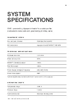
Page 29: ...ar Feed water source Municipal drinking water TREATMENT STEPS Pre and post filtration PCB filter PAC and PP RO membranes Aquaporin Inside DWRO 800 GPD TECHNICAL SPECIFICATIONS Permeate flow rate 1 75 L min Water recovery rate 65 DWRO membrane output 7200 L PAC filter output 4000 L Power Supply Voltage Frequency 220 240V 50Hz Power consumption 80W Technical specifications are tested with 25 2 C wat...

Page 30: ...ONE Installation guide EN Revised 15 MAR 2021 Aquaporin A S Nymøllevej 78 2800 Kongens Lyngby Denmark VAT No DK28315694 Tel 45 82 30 30 82 sales aquaporin com aquaporin com ...

Reviews: