background image


WARNING: Using a qualified installer is recommended.


Proper installation is the responsibility of the installer.


Product failure due to improper installation is not covered under the warranty.

NOTE: Keep these instructions for future reference

PLAN FOR INSTALLATION

Prior to installation, we recommend you read the entire manual to familiarize yourself with the 
system, and help you determine the best location for installation. Please check and comply with 
all local plumbing codes.

PREPARE SITE FOR INSTALLATION


NOTE: If you have metal drain pipes, consult a plumber for installation of drain connection.

1.  Prior to installation, close the cold water shut-off valve.

2.  Temporarily place system manifold, remineralizer, and  

tank into the under sink cabinet or desired location  
to ensure adequate space and proper positioning. 

3.  3/8" white tubing will be used to connect manifold to tank, and from faucet stem to 

remineralizer. Measure out 3/8" white tubing from the top of the tank to the outlet side of the 
system manifold and mark 3/8" tubing. Then measure remaining length of 3/8" tubing from the 
remineralizer to the desired location of the faucet hole to ensure there will be enough 3/8" 
tubing available for both connections. Wait to cut tubing and follow instructions below.

4.  Remove system, remineralizer, and tank from under your sink to begin installation.

INSTALLATION OVERVIEW

Step 1

 - Install Brass Tee Fitting

Step 2

 - Install RO System Manifold

Step 3

 - Install Water Storage Tank

Step 4

 - Install RO Faucet

Step 5

 - Install RO Drain Connector

Step 6

 - Connect Tubing

Step 7

 - Stage 1–3 Filter Installation

Step 8

 - Sanitize, Pressure Test, Purge System

REQUIRED TOOLS & MATERIALS

• Basic plumbing knowledge

• Tape Measure

• Utility Knife

• Screwdriver (Phillips)

• 1/8" & 7/32" Drill Bits/Drill

• Adjustable Wrench

• Bleach

• Safety Glasses

• Pencil

• Masking Tape

• Pan or Bucket

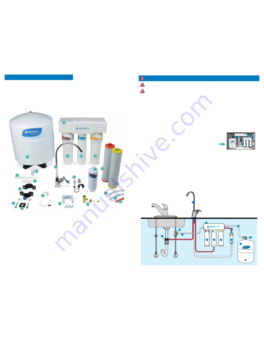
WHAT’S INCLUDED

A  System Manifold

B   Carbon Filter Sump

C   Membrane Filter Sump

D   Claryum Filter Sump

E   Remineralizer

F   Faucet

G  Gasket, Nut, Washer, Spacer, 

  Quick Connector (for faucet)

H  Water Storage Tank

I  Eye Dropper

J  Tank Connector

K  Plumber’s Tape

L  Drain Connector

M  Nuts & Bolts

N  Foam Seal

O  Flow Restrictor & 

  90° Elbow 

P  Tubing 1/4" White

Q  Tubing 3/8" White

R  Tubing 3/8" Red

S   Bracket

T  Brass Tee

U  Carbon Filter Cartridge

V  Claryum Filter Cartridge

HOT

OptimH2O™

Stage 2

RO Membrane

AQ-RO3-RO

OptimH2O™

OptimH2O™

Remineralizer

AQ-RO3-RM

COLD

A

B

D

C

E

F

G

H

L

T

R

Q

P

J

A

B

F

G

H

I

J

K

L

M

N

O

P

Q

R

S

T

U

V

C

D

E

OptimH2O™

Summary of Contents for OptimH2O AQ-RO-3

Page 1: ...ter technology is working for you System tested and certified by NSF International against NSF ANSI Standard 42 53 401 and conforms to NSF protocol P473 for reduction of claims specified on the Perfor...

Page 2: ...aucet hole to ensure there will be enough 3 8 tubing available for both connections Wait to cut tubing and follow instructions below 4 Remove system remineralizer and tank from under your sink to begi...

Page 3: ...RO3 RO OptimH2O OptimH2O A B C D E F OptimH2O OptimH2O OptimH2O OptimH2O OptimH2O OptimH2O OptimH2O A B C 2 1 2 INSTALL SYSTEM MANIFOLD 1 Select an easily accessible area under the sink to mount syste...

Page 4: ...cet 5 INSTALL RO DRAIN CONNECTOR WARNING CAUTION Be sure that all electrical appliances and outlets are turned off at the circuit breaker before working in the cabinet area Please wear safety glasses...

Page 5: ...Membrane red tubing from faucet 1 Insert restrictor into the end of the red tubing 2 Attach red tubing to the 90 elbow until it stops 3 Attach 90 elbow to the membrane drain port VI Faucet to Drain C...

Page 6: ...ing end If there are squarely cut 1 off and re insert Note When RO Filter System is first pressurized water may project from faucet air gap hole until air is passed from RO Filter System Purge 1 Open...

Page 7: ...the scaling and fouling tendencies of the Feed Water 2 Measured at 50 psi 77 2 F and 717 mg l TDS per NSF ANSI Standard 58 3 Efficiency rating means the percentage of the influent water to the system...

Page 8: ...y filled flush saturate the remineralizer cartridge by opening up the filter faucet and allowing the purified water to run through the remineralizer for 3 minutes The water may come out cloudy during...

Page 9: ...oroethylene 0 007 0 083 0 001 99 cis 1 2 dichloroethylene 0 07 0 170 0 0005 99 trans 1 2 dichloroethylene 0 1 0 086 0 001 99 1 2 dichloropropane 0 005 0 080 0 001 99 cis 1 3 dichloropropylene 0 079 0...

Page 10: ...hibit the exclusion or limit of incidental or consequential damages so the above limitation or exclusion may not apply to you WARRANTY CARD Warranty registration is not required for coverage under the...

Page 11: ...s to NSF protocol P473 for reduction of claims specified on the Performance Data Sheet and at nsf org The AQ RO 3 system has been tested and certified by NSF International against NSF ANSI Standard 58...

Reviews: